


ASSEMBLY INSTRUCTIONS
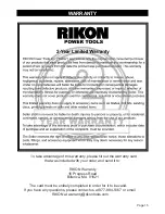
INSTALL THE BUFFING WHEELS
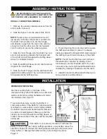
1. Remove the plastic protective sleeves from the
arbor shafts, if present.
2. Slide the Spacer onto the arbor shaft. FIG. E.
NOTE:
Spacers are not required when mount
-
ing several, or thicker, wheels are mounted onto
the shaft. Their purpose is to set the flanges
and wheel(s) away from the step in the arbor far
enough so that the arbor nuts can be threaded
onto the arbor to secure the wheels in place.
3. Slide the Inner Flange onto the shaft. The ‘cup’
side should be facing towards the threaded end
of the shaft, and will be against the buffing wheel
when it is installed in step 4.
4. Slide the Buffing Wheel onto the shaft and butt
it against the inner flange.
5. Slide the Outer Flange onto the shaft and butt it
against the buffing wheel. The ‘cup’ side should be
facing towards the buffing wheel.
Page 10
6. Thread the Arbor Nut onto the shaft to secure
the buffing wheel firmly in place. The places
pressure against the flanges which press against
the buffing wheel to hold it in place on the shaft.
NOTE:
The left hand arbor hex nut is left hand
threaded and is installed by rotating it coun
-
terclockwise onto the threaded shaft. The right
hand arbor hex nut is right hand threaded and is
linstalled by rotating it clockwise onto the shaft.
7. Install the second buffing wheel following the
same procedure outlined above.
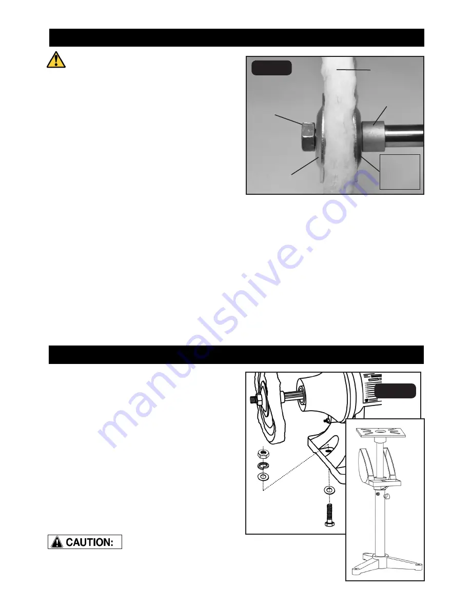
INSTALLATION
PERMANENT MOUNTING
Use the mounting holes in the base of the
machine to firmly attach the Buffer to a solid work
surface or stand (mounting hardware and stand
not included). See Figure F.
To avoid serious injury, secure the Buffer to a
solid work surface. If the Buffer is not permanently
mounted to a work surface, and remains portable,
the Buffer’s base should be temporarily clamped
to a table or board/plywood. Make sure that the
clamps do not interfere with the buffing wheels or
hinders the movement of the user and the material
during use.
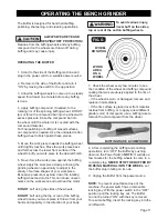
FIG. F
If the Buffer is not securely mounted, it will have the
ability to move or tip over during buffing operations, and possibly cause the
operator’s fingers to contact the rotating wheels, damage to the work piece
being buffed, or damage the buffer and any surrounding shop items.
THE BUFFER MUST NOT BE PLUGGED IN
AND THE POWER SWITCH MUST BE IN THE
OFF POSITION UNTIL ASSEMBLY IS COMPLETE
.
SPACER
INNER
FLANGE
OUTER
FLANGE
BUFFING
WHEEL
LH NUT
FIG. E
HARDWARE
RECOMMENDED
FOR MOUNTING
THE BUFFER
WORK
STAND


