


Start-up, calibration and operation of the burner
20008423
31
GB
5.7
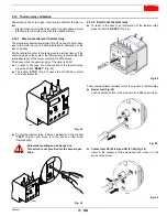
Final calibration of the pressure switches
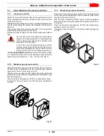
5.7.1
Air pressure switch
Adjust the air pressure switch after having performed all other
burner adjustments with the air pressure switch set to the start
of the scale (Fig. 35).
With the burner operating at min. output, increase adjustment pres-
sure by slowly turning the relative dial clockwise until the burner
locks out.
Then turn the dial anti-clockwise by about 20% of the set point and
repeat burner starting to ensure it is correct.
If the burner locks out again, turn the dial anti-clockwise a little bit
more.
As a rule, the air pressure switch must prevent the air
pressure from lowering below 80% of the adjustment
value as well as preventing the CO in the fumes from
exceeding 1% (10,000 ppm).
To check this, insert a combustion analyser into the
chimney, slowly close the fan suction inlet (for ex-
ample with cardboard) and check that the burner
locks out, before the CO in the fumes exceeds 1%.
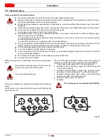
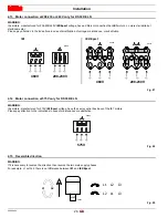
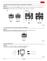
On
RS 300-400-500/E burners
the air pressure switch is fitted
in a "differential" mode, that is, with two pipes connected to the
specific pressure test points “+” and “-” 22) and 23) (Fig. 5).
5.7.2
Maximum gas pressure switch
Adjust the maximum gas pressure switch after having performed
all other burner adjustments with the maximum gas pressure
switch set to the end of the scale (Fig. 39).
With the burner operating at MAX output, reduce the adjustment
pressure by slowly turning the adjustment dial anticlockwise until
the burner locks out.
Then turn the dial clockwise by 0.8” WC and repeat burner firing.
If the burner locks out again, turn the dial again clockwise by
0.4” WC.
5.7.3
Minimum gas pressure switch
Adjust the minimum gas pressure switch after having performed
all the other burner adjustments with the pressure switch set at
the start of the scale (Fig. 40).
With the burner operating at MAX output, increase adjustment
pressure by slowly turning the relative dial clockwise until the burn-
er locks out.
Then turn the dial anti-clockwise by 0.8” WC and repeat burner
starting to ensure it is uniform.
If the burner locks out again, turn the dial anti-clockwise again by
0.4” WC.
ATTENTION
Fig. 39
D9272
Fig. 40
D9290


