


20008423
23
GB
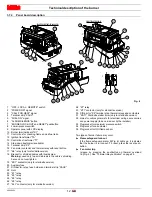
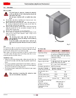
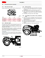
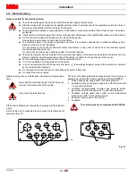
4.10.2 Gas feeding line
It must be type-approved according to required standards and is
supplied separately from the burner.
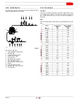
Key to lay-out (Fig. 20)
1
Gas input pipe for main burner
2
Manual valve
3
Low gas pressure switch
4
Safety shut-off valve
5
NO vent valve
6
Regulating shut off valve
7
Gas input pipe for pilot
8
Gas adjustment butterfly valve
9
Burner
10 High gas pressure switch
11 Manual valve (for seal control)
12 Pilot regulator
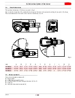
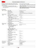
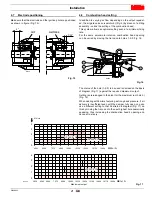
4.10.3 Gas pressure
Important
The pressure at the head of the burner from table refers to zero
in the combustion chamber; to obtain true pressure, measured
by a U-type manometer, (Fig. 36) add the counter-pressure of
the boiler.
Note
See the accompanying instructions for the adjustment of the gas
train.
Mai n
gas suppl y
10
2
3
4
5
6
11
Vent
2
12
5
4
7
Vent
9
8
1
4
D3776
Fig. 20
GCV
MBtu/hr
Combustion
Head
“WC
Gas but
Adaptor
“WC
R
S
30
0/E L
N
5112
3.3
0.63
5680
3.7
0.79
7574
4.9
1.38
9467
5.4
2.13
11361
5.9
3
13254
7.9
4.2
14390
9
5.1
R
S
40
0/E
L
N
6816
2.3
1.1
7574
3
1.38
9467
4.7
2.13
11361
6.4
3
12307
7.3
3.62
13254
8.3
5.17
15148
10.8
5.47
17042
13
7
RS 50
0/E L
N
9467
4.4
1.81
11361
6
2.64
13254
7.7
3
15148
9.7
3.82
17042
11.8
4.64
18935
14.1
5.55
19692
15
5.9


