


20008423
12
GB
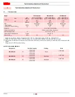
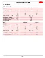
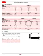
Technical description of the burner
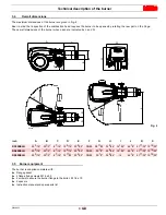
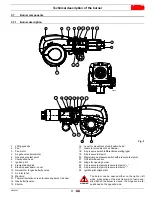
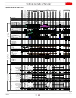
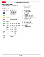
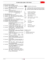
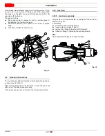
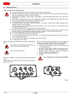
3.7.2
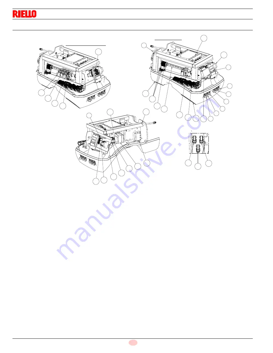
Panel board description
1
“OFF - LOCAL - REMOTE” switch
2
“POWER ON” signal
3
“CALL FOR HEAT” signal
4
Terminal strip “XAUX”
5
“FUEL ON” signal
6
“ALARM SILENCE” button
7
“BURNER LOCK-OUT and RESET” pushbutton
8
Low air pressure switch
9
Operator panel with LCD display
10 Burner terminal board “X1”
11 Control box for checking flame and air/fuel ratio
12 Ignition transformer “TA”
13 Control box trasformer “T1”
14 Step-down trasformer (available)
15 Terminal strip “X2”
16 Fan motor contactor and thermal relay with reset button
17 “K6” relay (only for star/delta version)
18 Bracket for shielded cables with thumbscrew
Warning:
used only to avoid a break in the cable’s shielding,
hence do not overtighten.
19 “KS1” contactor (only for star/delta version)
20 Auxiliary fuse
21 DIN bar for: relay, fuse holder and terminal strip “XAUX”
22 Horn
23 ”K1” relay
24 “K3” relay
25 “K5” relay
26 “K2” relay
27 “KL1” contactor (only for star/delta version)
28 “K7” relay
29 “KT1” contactor (only for star/delta version)
30 DIN bar for “X2” terminal strip, thermal relays and contactors
31 “KST1” Star/delta starter timer (only for star/delta version)
32 Holes for cables grommets for electrical wirings, accessories
and power supply (to be carried out by the installer)
33 Plug/socket for maximum pressure switch
34 Plug/socket for air actuator
35 Plug/socket for QRI flame sensor
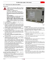
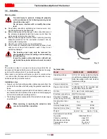
Two types of burner failure may occur:
Flame safeguard lock-out
If the flame safeguard alarm 6)(Fig. 6) lights up, it indicates
that the burner is in lock-out. To reset, press the reset push-
button.
Fan motor trip
release by pressing the pushbutton on thermal overload
16)(Fig. 6). See “Thermal relay calibration” on page 25.
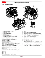
*
DIRECT START (RS 300/E)
11
20
9
14
7
6
5
3
2
1
32
10
16
15
18
32
30
8
24
13
12
23
21
28
25
4
22
26
*
33
34
35
START / DELTA START (RS 400-500/E)
17
31
29
19
27
Fig. 6
D11897


