


20008423
28
GB
Start-up, calibration and operation of the burner
5.1
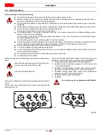
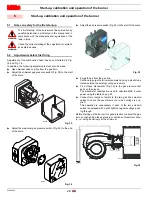
Notes on safety for the first start-up
The first start-up of the burner must be carried out by
qualified personnel, as indicated in this manual and in
compliance with the standards and regulations of the
laws in force.
Check the correct working of the adjustment, command
and safety devices.
5.2
Adjustments before first firing
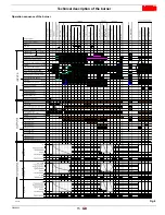
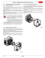
Adjustment of the combustion head has been illustrated in Fig.
16 and Fig. 18.
In addition, the following adjustments must also be made:
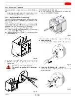
Open manual valves up-line from the gas train.
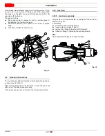
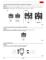
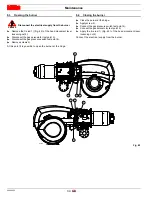
Adjust the minimum gas pressure switch (Fig. 33) to the start
of the scale.
Adjust the maximum gas pressure switch (Fig. 34) to the end
of the scale.
Adjust the air pressure switch (Fig. 35) to the start of the scale.
Purge the air from the gas line.
Continue to purge the air (we recommend using a plastic tube
routed outside the building) until gas is smelt.
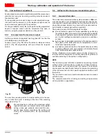
Fit a U-type manometer (Fig. 36) to the gas pressure test
point on the sleeve.
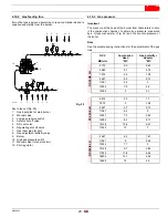
The manometer readings are used to calculate MAX. burner
power using the table on pag. 23.
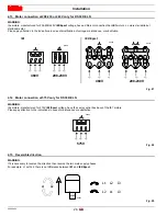
Connect two lamps or testers to the two gas line solenoid
valves to check the exact moment at which voltage is sup-
plied.
This operation is unnecessary if each of the two solenoid
valves is equipped with a pilot light that signals voltage pass-
ing through.
Before starting up the burner it is good practice to adjust the gas
train so that ignition takes place in conditions of maximum safe-
ty, i.e. with gas delivery at the minimum.
5
Start-up, calibration and operation of the burner
WARNING
WARNING
Fig. 33
D9290
Fig. 34
D9272
Fig. 35
D3854
D3100
Fig. 36


