Installation
13
20020804
4.5
Securing the burner to the boiler
4.5.1
Boring the boiler plate
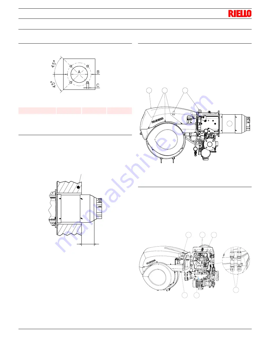
Drill the combustion chamber locking plate as shown in (Fig. 9).
Tab. 4
4.5.2
Blast tube length
The length of the blast tube must be selected according to the
indications provided by the manufacturer of the boiler, and in
any case it must be greater than the thickness of the boiler door
complete with its fettling (the head should not jut out more than
4÷5 inch).
4.5.3
Burner securing
Create a suitable hoisting system by hooking onto the rings
4), removing the fastening screws 1) securing the cover 2)
first.
Slip the thermal protection onto the blast tube 3).
Place entire burner on the boiler hole (arranged previously,
see Fig. 9), and fasten with the screws given as standard
equipment.
The coupling of the burner-boiler must be airtight.
4.5.4
Accessibility to the interior of the combustion
head
Open burner at hinge (see Fig. 12) after removing the 4
screws 1).
Disconnect the wires 2) from the electrodes.
Disconnect the oil pipes by unscrewing the two connectors 3).
Note: While unscrewing, some fuel may leak out.
Unscrew the under part of the elbow 4) until it comes free of
its slot.
Extract the internal part 5) of the combustion head.
mm
A
B
C
RLS 800/E US1
17 5/16“
19 31/64“
45/64 W
Fig. 9
D455
4 ÷ 6 "
REFRACTORY MATERIAL
D10002
Fig. 10
REFRACTORY MATERIAL
1
4
2
3
D10003
Fig. 11
Fig. 12
1
4
1
2
5
3
A
D3508
Содержание RLS Series
Страница 2: ......
Страница 34: ...20020804 32 Appendix Electrical panel layout ...
Страница 35: ...Appendix Electrical panel layout 33 20020804 ...
Страница 36: ...20020804 34 Appendix Electrical panel layout ...
Страница 37: ......
Страница 38: ......
Страница 39: ......


