background image

13 

2902936

I

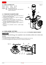
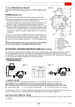
4.5 REGOLAZIONE ARIA,

 (fig. 19)

In funzione della potenza del bruciatore, è necessario rego-
lare l’aria mediante la rotazione dell’adduttore (2) e succes-
sivamente della manopola (3).

Per la regolazione procedere come segue:

Allentare le tre viti (1).

Ruotare  l’adduttore  (2)  posizionandolo  secondo  i  valori
riportati nella tabella a pagina 11. 

Avvitare le tre viti (1) con coppia di serraggio non superiore
a 0,8 Nm.

Attenzione
E’ importante assicurare il corretto serraggio dell’adduttore
mediante le viti, al fine di evitare l’eventuale perdita di tara-
tura del bruciatore in funzionamento.

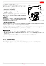
Si effettua ruotando la manopola (3). La rotazione in senso orario limita la sezione del passaggio d’aria e fa
aumentare il valore della CO

2

; in senso antiorario avviene il contrario. 

Le regolazioni riportate nella tabella a pagina 11, sono puramente indicative. 
Ogni impianto ha condizioni di funzionamento non prevedibili: portata effettiva dell’ugello, pressione o
depressione in camera di combustione, eccesso d’aria necessario; ecc.
Tutte queste condizioni possono richiedere una diversa regolazione dell’aria. 

Per nessun motivo deve essere ostruita l’entrata dell’aria nella zona manopola (3, fig. 19).

E’ vietato accedere all’interno dell’apertura di aspirazione della manopola (3, fig. 19) con le dita o qual-
siasi utensile.

Controllare la posizione dell’adduttore e della manopola come indicato in tabella a pagina 11.

Controllare il bacharach e la CO

2

.

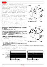
4.6 PRESSIONE POMPA

12 bar: La pompa lascia la fabbrica tarata a tale valore. 

14 bar: Migliora l’aggancio fiamma all’elica. È quindi indicata per le accensioni a basse temperature.

Fig. 19

D7004

1

1

1

2

3

REGOLAZIONE ADDUTTORE

REGOLAZIONE MANOPOLA

ATTENZIONE

Содержание RC2R

Страница 1: ...etien Installation use and maintenance instructions Bruciatori di gasolio Öl Gebläsebrenner Brûleurs fioul domestiques Light oil burners Funzionamento monostadio Einstufiger Betrieb Fonctionnement à 1 allure One stage operation CODICE CODE MODELLO MODELL MODEL TIPO TYP TYPE 3570050 RC2R 735T1 3571050 20069606 RC2R 735T3 3572050 RC2R 735T4 I D F GB ...

Страница 2: ......

Страница 3: ...combustione 11 4 2 Ugelli consigliati 12 4 3 Posizione di manutenzione 12 4 4 Regolazione elettrodi 12 4 5 Regolazione aria 13 4 6 Pressione pompa 13 4 7 Riscaldamento del combustibile 14 4 8 Ricerca guasti del dispositivo di riscaldamento 14 4 9 Programma di avviamento 14 5 MANUTENZIONE 15 5 1 Accessibilità alla girante 15 6 ANOMALIE RIMEDI 16 1 Ritorno 2 Aspirazione 3 Pompa olio 4 Attacco manome...

Страница 4: ...Hi 11 86 kWh kg Alimentazione elettrica Monofase 50Hz 230V 10 Motore 0 75A assorbiti 2800 g min 294 rad s Condensatore 4 5 µF Trasformatore d accensione Secondario 8 kV 16 mA Pompa Pressione 7 15 bar Potenza elettrica assorbita 0 15 kW D7010 4 5 4 5 180 130 150 11 75 72 120 146 109 191 85 183 256 D7001 16 18 20 22 24 26 28 30 32 34 36 38 40 1 5 2 5 2 3 0 1 2 3 14 D7017 Pressione in camera di combu...

Страница 5: ...a presa d aria 3 in posi zione orizzontale avendo cura di tirare il dispositivo di bloccaggio 6 fig 5 pag 4 ruotare il senso orario per fissare la presa aria 3 al bruciatore e rilasciare il dispositivo di bloccaggio 6 La presa aria può essere orientata in base alle esi genze d installazione come illustrato in figura 4 Per la regolazione è necessario agire sul dispositivo di bloccaggio 6 fig 5 pag ...

Страница 6: ... le due viti 11 avvitandole con coppia di serraggio di 0 8 Nm rimontare con procedura inversa a quanto sopra descritto riposizionando l adduttore 5 come in ori gine serrando le due viti 9 con coppia di serraggio non superiore a 0 8 Nm prestare molta attenzione al corretto posiziona mento dell anello di tenuta 12 3 INSTALLAZIONE L INSTALLAZIONE DEL BRUCIATORE DEVE ESSERE EFFETTUATA IN CONFORMITÀ AL...

Страница 7: ...cazione BF l alimentazione dell aria per la combu stione avviene attraverso un tubo flessibile o rigido collegato alla presa d aria B PER UNA CORRETTA APPLICAZIONE BF IL BRUCIATORE DEVE ESSERE INSTALLATO SU UNA APPROPRIATA CAL DAIA BF E necessario per tanto rispettare i seguenti requisiti ed indica zioni Il tubo di aspirazione dell aria comburente deve essere ben fissato al bruciatore di materiale...

Страница 8: ...tenzione la lunghezza si riduce nel caso in cui siano presenti curve nel tratto di aspirazione Per esempio utilizzando una tubazione con superficie interna liscia si devono considerare le seguenti perdite per ogni curva da 45 la lunghezza del tubo si riduce di 0 5 m per ogni curva da 90 la lunghezza del tubo si riduce di 0 8 m IL BRUCIATORE DEVE ESSERE INSTALLATO RISPETTANDO LE APPLICAZIONI RIPORT...

Страница 9: ...rbatoio ad altezza maggiore del bruciatore o sistemi di pompaggio del combustibile esterni al bruciatore La figura 12 è esemplificativa di un collegamento ad anello in pressione a prescindere dalla posizione del serbatoio di alimentazione dell anello stesso Nell impianto di fig 11 la tabella riporta le lunghezze massime indicative per la linea di alimentazione in fun zione del dislivello della lun...

Страница 10: ... alla stessa altezza della tubazione di aspirazione In questo caso non è necessaria la valvola di fondo Se invece la tubazione di ritorno arriva sopra il livello del combustibile la valvola di fondo è indispensabile Questa soluzione è meno sicura della precedente per la possibile mancanza di tenuta della valvola IMPIANTI IN DEPRESSIONE fig 13 e 14 H max 4 m max 4 m H H H D7008 H metri L metri ø i ...

Страница 11: ... tirare nel senso della freccia Percorso del cavo elettrico 1 Morsettiera N Neutro Segnalazione di blocco L Fase Terra bruciatore ACCESSIBILITÀ AL SENSORE FIAMMA vedi fig 16 Il sensore fiamma è montata direttamente nell ap parecchiatura sotto il trasformatore di accensio ne su un supporto ad innesto rapido S8180 A 1 Fig 15 Fig 16 Marrone Bianco 50V Motore Condensatore Neutro T6A N L M Nero 230V 50...

Страница 12: ...igenti nel paese ATTENZIONE Marrone Bianco Blu 50Hz 230V Marrone D10682 Nero Giallo Verde Rosso Rosso Blu Blu Marrone Grigio Nero ESEGUITO IN FABBRICA A CURA DELL INSTALLATORE Legenda C Condensatore F Fusibile T6A h Contaore H Segnalazione di blocco a distanza 230V 0 5A max MV Motore ventilatore Q Interruttore generale R Resistenza 55W TL Termostato limite TS Termostato di sicurezza V Valvola XP7 ...
Страница 13: ...golare la CO2 a 12 0 2 VERSIONE CON DEFLETTORE TIPO Ugello Pressione pompa Portata bruciatore Regolazione aria Pressione testa CF BF CF BF CF BF CF BF GPH Angolo bar kg h 4 Adduttore Manopola Adduttore Regolatore mbar Tacca Tacca Tacca Tacca 735T1 0 40 80 W 11 1 43 1 0 1 0 2 1 3 0 50 60 W 12 1 8 1 0 4 1 0 6 2 0 0 55 60 W 12 2 1 1 1 1 1 1 2 8 0 60 60 W 11 2 2 1 1 2 1 1 2 3 1 735T3 0 50 60 W 14 2 0 ...

Страница 14: ...urbolatore 3 dopo aver allentato la vite 3 fig 18 Avvitare l ugello 4 stringendolo come mostrato in figura 17 Rimontare con procedura inversa a quanto sopra descritto 4 4 REGOLAZIONE ELETTRODI Per accedere agli elettrodi eseguire l operazione descritta al capitolo 4 3 POSIZIONE DI MANUTENZIONE La posizione degli elettrodi non é regolabile In caso di anomalie verificare che le misure siano rispetta...

Страница 15: ...rario avviene il contrario Le regolazioni riportate nella tabella a pagina 11 sono puramente indicative Ogni impianto ha condizioni di funzionamento non prevedibili portata effettiva dell ugello pressione o depressione in camera di combustione eccesso d aria necessario ecc Tutte queste condizioni possono richiedere una diversa regolazione dell aria Per nessun motivo deve essere ostruita l entrata ...

Страница 16: ...a funziona è spenta quando la resistenza è disinserita o guasta 4 8 RICERCA GUASTI DEL DISPOSITIVO DI RISCAL DAMENTO FUNZIONAMENTO REGOLARE La spina infilata nel pannello dell apparecchiatura si trova nella posizione di resistenza inserita vedi fig 20 Alla chiusura del telecomando il LED si illumina e dopo circa due minuti si avvia il bruciatore MANCATO FUNZIONAMENTO DEL BRUCIATORE 1 Se il LED è s...

Страница 17: ... la pulizia della testa di combustione nella zona di uscita del combustibile Lasciare funzionare il bruciatore a pieno regime per circa dieci minuti tarando correttamente tutti gli ele menti indicati nel presente manuale Quindi effettuare un analisi della combustione verificando Temperatura dei fumi al camino Percentuale di CO2 Contenuto di CO ppm Indice di opacità dei fumi secondo la scala di Bac...

Страница 18: ...oni di legge vigenti ANOMALIE POSSIBILE CAUSA CONTROLLI E RIMEDI Il bruciatore non par te alla chiusura del termostato di limite Manca l alimentazione elettrica Verificare che il termostato di sicurezza non sia in blocco Verificare che il termostato di limite non sia guasto Verificare presenza tensione ai morsetti L N dell apparecchiatura di comando e controllo Apparecchiatura di comando e control...

Страница 19: ...temente la fiamma Pulirla o sostituirla La fiamma si stacca Ottimizzare la regolazione aria combustibi le CO2 Ugello inadeguato sporco o deteriorato so stituirlo La valvola non resta eccitata sostituire l ap parecchiatura di comando e controllo la bo bina o la valvola della pompa Filtri sporchi pulirli o sostituirli Avviamento del bru ciatore con ritardo di accensione Gli elettrodi d accensione so...

Страница 20: ......

Страница 21: ...schema 9 4 BETRIEB 11 4 1 Einstellung der Brennerleistung 11 4 2 Empfohlene Düsen 12 4 3 Wartungsposition 12 4 4 Elektrodeneinstellung 12 4 5 Lufteinstellung 13 4 6 Pumpendruck 13 4 7 Ölvorwärmung 14 4 8 Störungssuche des Ölvorwärmers 14 4 9 Betriebsablauf 14 5 WARTUNG 15 5 1 Zugänglichkeit zum Gebläserad 15 6 STÖRUNGEN ABHILFE 16 1 Rücklaufleitung 2 Saugleitung 3 Ölpumpe 4 Manometeranschluß 5 Dru...

Страница 22: ...osität 4 6 mm2 s a 20 C Hi 11 86 kWh kg Stromversorgung Einphasig 50Hz 230V 10 Motor Stromaufnahme 0 75A 2800 U min 294 rad s Kondensator 4 5 µF Zündtransformator Sekundärspannung 8 kV 16 mA Pumpe Druck 7 15 bar Leistungsaufnahme 0 15 kW D7010 4 5 4 5 180 130 150 11 75 72 120 146 109 191 85 183 256 D7001 Druck im Feuerraum mbar AUSFÜHRUNG OHNE ABWEISER CF BF 16 18 20 22 24 26 28 30 32 34 36 38 40 ...

Страница 23: ... 3 gezeigt den Luftanschluss 3 horizontal am Zuführer 5 anbringen und die Sperrvorrichtung 6 Abb 5 S 4 ziehen im Uhrzeigersinn drehen um den Luftanschluss 3 am Brenner zu befestigen und die Sperrvorrichtung 6 los lassen Der Luftanschluss kann je nach Installation aus gerichtet werden wie in Abbildung 4 gezeigt Für die Einstellung muss die Sperrvorrichtung 6 Abb 5 S 4 betätigt und der Luftanschluss...

Страница 24: ...uben 11 befestigen und diese mit 0 8 Nm Anzugsmoment blokkieren die erneute Montage auf umgekehrte Weise aus führen und den Zuführer 5 wieder wie ursprüng lich anbringen indem die beiden Schrauben 9 mit einem Anzugsmoment nicht über 0 8 Nm blokkiert werden sehr darauf achten dass der Dichtungsring 12 korrekt angebracht ist 3 INSTALLATION DIE INSTALLATION DES BRENNERS MUSS IN ÜBEREINSTIMMUNG MIT DE...

Страница 25: ...r Anwendung BF erfolgt die Verbrennungsluftzufuhr durch einen Schlauch oder ein Rohr der mit dem Luftanschluss B verbunden ist FÜR EINEN KORREKTEN RAUMLUFTUNABHÄNGIGEN BETRIEB MUSS DER BRENNER AN EINEN FÜR RAUMLUFTUN ABHÄNGIGEN BETRIEB GEEIGNETEN HEIZKESSEL MONTIERT WERDEN Daher sind folgende Anforderungen und Hinweise einzuhalten Der Saugschlauch der Verbrennungsluft muss wie folgt sein er muss g...

Страница 26: ...iert sich falls Bogen in der Saugstrecke vorhanden sind Wenn zum Beispiel ein Rohr mit glatter Innenfläche benutzt wird sind folgende Verluste zu berücksich tigen für jeden 45 Bogen reduziert sich die Höchstlänge des Rohrs um 0 5 m für jeden 90 Bogen reduziert sich die Höchstlänge des Rohrs um 0 8 m DER BRENNER MUSS UNTER BEACHTUNG DER INSTALLATIONSARTEN AUF DEN ABBILDUNGEN UNTEN INSTALLIERT WERDE...

Страница 27: ...Tank liegt gewöhnlich höher als der Brenner oder Brennstoff Pumpsysteme außerhalb des Brenners In Abbildung 12 ist ein Beispiel eines Anschlusses an unter Druck stehendem Flammkopf gezeigt abgesehen von der Position des Versorgungstanks des Flammkopfes selbst Für die Anlage in Abb 11 sind die ungefähren Höchstlängen der Zuleitung in Abhängigkeit vom Höhenunter schied der Länge und des Durchmessers...

Страница 28: ...gleicher Höhe wie die Saugleitung im Tank enden zu lassen Es kann auf ein Fußventil in der Saugleitung verzichtet werden Endet die Rücklaufleitung über dem Ölniveau wird auf der Saugseite zwingend ein Fußventil benötigt wobei dieses dann bei Verschmutzung Probleme verursachen kann ANLAGEN MIT UNTERDRUCK Abb 13 und 14 H max 4 m max 4 m H H H D7008 H Meter L Meter ø i 8 mm ø i 10 mm 0 0 5 1 1 5 2 3 ...

Страница 29: ...it Schnellanschluss montiert NULLEITER NICHT MIT DER PHASE VERWECHSELN ANMERKUNGEN Leiterdurchmesser min 1 mm2 Außer im Falle anderslautender Angaben durch Normen und örtliche Gesetze Die vom Installateur ausgeführten elektrischen Verbindungen müssen den lokalen Bestimmungen entsprechen WICHTIGER HINWEIS Zündtransformator Flammenfühler S7057 Abb 15 Abb 16 Braun Weiss 50V Blau Motor Kondensator Nul...

Страница 30: ...ndun gen müssen den lokalen Bestimmungen entsprechen WICHTIGER HINWEIS Braun Weiß Blau 50Hz 230V Braun D10682 Schwarz Rot Rot Blau Blau Braun Grey Schwarz WERKSEITIGE EINSTELLUNG VOM INSTALLATEUR AUSZUFÜHREN Zeichenerklärung C Kondensator F Sicherung T6A h Betriebsstundenzähler H Störungsanzeige Fernmeldung 230V 0 5A max MV Motor Q Hauptschalter R Vorwärmer 55W TL Grenzthermostat TS Sicherheitsthe...

Страница 31: ...Pumpen Druck Brenner Durchsatz Lufteinstellung Kopfdruck CF BF CF BF CF BF CF BF GPH Winkel bar kg h 4 Zufuhr Drehknopf Zufuhr Regler mbar Raste Raste Raste Raste 735T1 0 40 80 W 11 1 43 1 0 1 0 2 1 3 0 50 60 W 12 1 8 1 0 4 1 0 6 2 0 0 55 60 W 12 2 1 1 1 1 1 1 2 8 0 60 60 W 11 2 2 1 1 2 1 1 2 3 1 735T3 0 50 60 W 14 2 0 4 0 6 4 1 1 3 1 4 0 60 60 W 12 2 3 4 1 4 4 1 5 1 7 0 65 60 W 12 2 5 4 1 7 4 1 7...

Страница 32: ...b 18 aus dem Düsenstock herausnehmen Die Düse 4 anschrauben und anziehen wie in Abbil dung 17 gezeigt Die erneute Montage umgekehrt ausführen 4 4 ELEKTRODENEINSTELLUNG Um Zugang zu den Elektroden zu erhalten den im Kapitel 4 3 WARTUNGSPOSITION beschriebenen Vor gang ausführen Die Position der Elektroden ist nicht einstellbar Im Störungsfall prüfen dass die Maße eingehal ten sind Für die anderen Ei...

Страница 33: ...rzeigersinn erfolgt das Gegenteil Die in der Tabelle auf Seite 11 angegebenen Einstellwerte dienen nur als Hinweis Jede Anlage hat unvorhersehbare Betriebsbedingungen wie effektiver Düsendurchsatz Druck oder Nieder druck in der Brennkammer Überschuss an notwendiger Luft usw Der Lufteinlass im Drehknopfbereich 3 Abb 19 darf keinesfalls verstopft sein Es ist verboten die Finger oder Werkzeug in die ...

Страница 34: ...nn der Widerstand in Betrieb ist wenn der Widerstand ausgeschaltet oder defekt ist leuchtet sie nicht 4 8 STÖRUNGSSUCHE DES ÖLVORWÄRMERS REGULÄRER BETRIEB Der in der Grundplatte des Steuergeräts eingesteckte Stecker befin det sich in der Position Widerstand eingeschaltet Siehe Abb 20 Bei abgeschaltenem Telekommando leuchtet die LED auf und nach ca 2 Minuten läuft der Brenner an DER BRENNER STARTEN...

Страница 35: ...nd die korrekte Stellung der Elektroden überprüfen Abb 18 Den Brennkopf in der Brennstoffauslaufzone reinigen Brenner ca 10 Minuten auf voller Leistung laufen lassen alle in diesem Handbuch aufgeführten Ele mente korrekt einstellen Danach Abgasanalyse erstellen Abgastemperatur CO2 Gehalt CO Gehalt ppm Rußtest 5 1 ZUGÄNGLICHKEIT ZUM GEBLÄSERAD siehe Abb 22 WICHTIG Die Wartung nur wenn nötig ausführ...

Страница 36: ...gemäß den gel tenden gesetzlichen Vorschriften und Normen durchgeführt werden STÖRUNGEN MÖGLICHE URSACHE ABHILFE Der Brenner fährt beim Schließen des Regelthermostats nicht an Stromausfall Überprüfen ob der Sicherheitstemperatur begrenzer von Hand entriegelt werden muss Prüfen ob der Regelthermostat defekt ist Prüfen ob Spannung an den Klemmen L und N des Steuergeräts vorhanden ist Steuergerät def...

Страница 37: ...rt Der lichtelektrische Widerstand nimmt die Flamme nicht genügend wahr Reinigen oder auswechseln Die Flamme trennt sich ab Luft Brennstoffeinstellung CO2 optimie ren Düse nicht geeignet schmutzig oder beschädigt auswechseln Das Ventil bleibt nicht erregt Steuergerät Spule oder Ventil der Pumpe auswech seln Filter schmutzig reinigen oder auswech seln Anfahren des Bren ners mit Zündverzug Die Zünde...

Страница 38: ......

Страница 39: ...Réglage de la combustion 11 4 2 Gicleur conseillés 12 4 3 Position d entretien 12 4 4 Réglage des électrodes 12 4 5 Réglage air 13 4 6 Pression de la pompe 13 4 7 Réchauffage du combustible 14 4 8 Recherche des defauts dans le rechauffeur 14 4 9 Programme de mise en marche 14 5 ENTRETIEN 15 5 1 Accès au turbine 15 6 PANNES REMEDES 16 1 Retour 2 Aspiration 3 Pompe fioul 4 Raccord manomètre 5 Régula...

Страница 40: ...s à 20 C Hi 11 86 kWh kg Alimentation électrique Monophasée 50Hz 230V 10 Moteur 0 75A absorbés 2800 t min 294 rad s Condensateur 4 5 µF Transformateur d allumage Secondaire 8 kV 16 mA Pompe Pression 7 15 bar Puissance électrique absorbée 0 15 kW D7010 4 5 4 5 180 130 150 11 75 72 120 146 109 191 85 183 256 D7001 Pression dans la chambre de combustion mbar VERSION SANS DEFLECTEUR CF BF 16 18 20 22 ...

Страница 41: ...ion horizontale en ayant soin de tirer le dispositif de blo cage 6 fig 5 page 4 tourner dans le sens des aiguilles d une montre pour fixer la prise d air 3 au brûleur et relâcher le dispositif de blocage 6 La prise d air peut être orientée selon les exigences d installation comme indiqué sur la figure 4 Pour le réglage il est nécessaire d agir sur le dispositif de blocage 6 fig 5 page 4 et de tour...

Страница 42: ...eux vis 11 en les vissant avec un couple de serrage de 0 8 Nm remonter en procédant de la même façon mais en sens inverse Remettre l adducteur 5 comme il était à l origine en serrant les deux vis 9 avec un couple de serrage non supérieur à 0 8 Nm veiller à ce que la bague d étanchéité 12 soit bien placée 3 INSTALLATION LE BRÛLEUR DOIT ÊTRE INSTALLÉ CONFORMÉMENT AUX LOIS ET AUX RÉGLEMENTATIONS LOCA...

Страница 43: ...cation BF l alimentation de l air pour la com bustion a lieu grâce à un tuyau flexible ou rigide relié à la prise d air B POUR QUE L APPLICATION SOIT CORRECTE LE BRÛLEUR DOIT ÊTRE INSTALLÉ SUR UNE CHAUDIÈRE BF APPROPRIÉE Il est donc nécessaire de respecter les conditions et indications suivantes Le tuyau d aspiration de l air comburant doit être bien fixé au brûleur constitué d un matériau appropr...

Страница 44: ...de 6 mètres Attention la longueur se réduit s il y a des coudes dans le tronçon d aspiration Il faut considérer les fuites suivantes en utilisant par exemple un tuyau dont l intérieur est lisse pour chaque coude de 45 la longueur du tuyau se réduit de 0 5 m pour chaque coude de 90 la longueur du tuyau se réduit de 0 8 m LE BRÛLEUR DOIT ÊTRE INSTALLÉ EN RESPECTANT LES APPLICATIONS REPORTÉES SUR LES...

Страница 45: ...oir plus haut que le brûleur ou des systèmes de pompage du combustible à l extérieur de celui ci La figure 12 montre un branchement sous pression en anneau indépendamment de la position du réservoir d alimentation Dans l installation de la fig 11 le tableau reporte les longueurs maximums à titre indicatif pour la ligne d ali mentation en fonction de la dénivellation de la longueur et du diamètre d...

Страница 46: ...de retour doit arriver à la même hauteur que celle d aspiration Dans ce cas il n y a pas besoin de clapet de pied Dans le cas contraire le clapet de pied est indispensable Cette deuxième solution est moins sûre que la précédente en raison du manque d étanchéité éventuel de ce clapet INSTALLATIONS PAR DÉPRESSION fig 13 et 14 H max 4 m max 4 m H H H D7008 H mètres L mètres ø i 8 mm ø i 10 mm 0 0 5 1...

Страница 47: ...ûleur dévis ser la vis A et tirer du côte de la flèche Trajet des cables electriques 1 Bornier N Neutre Lampe sécurité L Phase Terre brûleur ACCES A LE CAPTEUR FLAMME voir fig 16 Le capteur flamme est montée directement sur la boîte de contrôle au dessous du transformateur d allumage sur un support à embrochage rapide Fig 15 Fig 16 Transformateur d allumage Capteur flamme S8180 1 NE PAS INVERSER L...

Страница 48: ...especter le règlement en vigueur dans le Pays ATTENTION Seulement pour 20069606 Blanc Bleu 50Hz 230V Brown D10682 Noir Jaune Vert Rouge Rouge Bleu Bleu Brown Gris Noir REALISE EN USINE A LA CHARGE DE L INSTALLATEUR Légende C Condensateur F Fusible T6A h Compteur d heures H Signalisation de blocage à distance 230V 0 5A max MV Moteur Q Interrupteur général R Résistance 55W TL Thermostat limite TS Th...

Страница 49: ...er le CO2 à 12 0 2 VERSION AVEC DÉFLECTEUR TYPE Gicleur Pression pompe Pression pompe Réglage de l air Pression tête CF BF CF BF CF BF CF BF GPH Angle bar kg h 4 Adducteur Bouton Adducteur Régulateur mbar Index Index Index Index 735T1 0 40 80 W 11 1 43 1 0 1 0 2 1 3 0 50 60 W 12 1 8 1 0 4 1 0 6 2 0 0 55 60 W 12 2 1 1 1 1 1 1 2 8 0 60 60 W 11 2 2 1 1 2 1 1 2 3 1 735T3 0 50 60 W 14 2 0 4 0 6 4 1 1 3...

Страница 50: ...rès avoir desserré la vis 3 fig 18 Visser le gicleur 4 en le serrant comme indiqué sur la figure 17 Remonter en procédant de la même façon mais en sens inverse 4 4 REGLAGE DES ELECTRODES Pour accéder aux électrodes effectuer l opération décrite voir chapitre 4 3 POSITION D ENTRETIEN La position des électrodes n est pas réglable En cas d anomalies vérifier si les mesures sont res pectées Procéder c...

Страница 51: ...ire Les réglages ne sont reportés qu à titre indicatif sur le tableau de la page 11 Chaque installation a des conditions de fonctionnement imprévisibles débit effectif du gicleur pression ou dépression dans la chambre de combustion excès d air nécessaire etc Toutes ces conditions peuvent amener à régler l air différemment Ne boucher en aucun cas l entrée de l air dans la zone du bouton 3 fig 19 Il...

Страница 52: ...d la résistance fonctionne elle est OFF quand la résistance est annulée ou en panne 4 8 RECHERCHE DES DEFAUTS DANS LE RECHAUFFEUR FONCTIONNEMENT REGULIER La fiche placée sur le panneau de la boîte est dans la position cor respondante à Résistance ON voir fig 20 A la fermeture de la télécommande le LED s illumine et après deux minutes env le brûleur démarre LE BRULEUR NE DEMARRE PAS 1 Si le LED est...

Страница 53: ...placées correctement fig 18 Nettoyer la tête de combustion dans la zone de sortie du combustible Laisser fonctionner le brûleur à plein régime pendant 10 minutes environ en contrôlant tous les paramètres indiqués dans ce manuel Après effectuer une analyse de la combustion en vérifiant Température des fumées de la cheminée Le pourcentage de CO2 Contenu de CO ppm L indice d opacité des fumées selon ...

Страница 54: ...ispositions légales en vigueur PANNES CAUSE POSSIBLE CONTROLES ET REMEDES Le brûleur ne dé marre pas à la ferme ture du thermostat de limite Absence d alimentation électrique Vérifier que le thermostat de sécurité ne soit pas intervenu Vérifier si le thermostat de limite n est pas en panne Vérifier s il y a de la tension aux bornes L N de la boîte de contrôle Boîte de contrôle défectueuse la rempl...

Страница 55: ...iser le réglage air combustible CO2 Gicleur inadéquat sale ou détérioré le remplacer La vanne ne reste pas excitée remplacer la boîte de contrôle la bobine ou la vanne de la pompe Filtres sales les nettoyer ou les remplacer Démarrage du brû leur avec retard d al lumage Les électrodes d allumage sont mal réglées Les régler selon les indications dans ce ma nuel Rapport air combustible pas correct Op...

Страница 56: ......

Страница 57: ...ombustion adjustment 11 4 2 Nozzles recommended 12 4 3 Maintenance position 12 4 4 Electrodes adjustment 12 4 5 Air adjustment 13 4 6 Pump pressure 13 4 7 Fuel heating 14 4 8 Failure detection on heating device 14 4 9 Burner start up cycle 14 5 MAINTENANCE 15 5 1 Access to the fan 15 6 FAULTS SOLUTIONS 16 1 Return line 2 Suction line 3 Oil pump 4 Gauge connection 5 Pressure adjuster 6 Control box ...

Страница 58: ...t 20 C Hi 11 86 kWh kg Electrical supply Single phase 50Hz 230V 10 Motor Run current 0 75A 2800 rpm 294 rad s Capacitor 4 5 µF Ignition transformer Secondary 8 kV 16 mA Pump Pressure 7 15 bar Absorbed electrical power 0 15 kW D7010 4 5 4 5 180 130 150 11 75 72 120 146 109 191 85 183 256 D7001 Pressure in combustion chamber mbar VERSION WITHOUT BAFFLE PLATE CF BF 16 18 20 22 24 26 28 30 32 34 36 38...

Страница 59: ...zontally against the feeder 5 making sure you pull the locking device 6 fig 5 page 4 turn clockwise to fasten the air intake 3 to the burner and release the locking device 6 The air intake can be turned to meet installation needs as illustrated in figure 4 To adjust you must pull the locking device 6 fig 5 page 4 and turn the air intake until you are happy with the position VERSION WITH BAFFLE PLA...

Страница 60: ...y means of the two screws 11 screwing it on with a driving torque of 0 8 Nm follow the above procedure in the reverse order restoring the feeder 5 to its original position tight ening the two screws 9 with a driving torque not exceeding 0 8 Nm make extra sure you position the O ring 12 cor rectly 3 INSTALLATION THE BURNER MUST BE INSTALLED IN CONFORMITY WITH LEGISLATION AND LOCAL STANDARDS 3 1 WOR...

Страница 61: ...n combustion air is fed through a flexible or rigid pipe connected to the air intake B FOR CORRECT BF APPLICATION THE BURNER MUST BE INSTALLED ON AN APPROPRIATE BF BOILER Consequently you must comply with the following requirements and instructions The combustion air intake tube must be fastened securely to the burner made of a suitable material with temperature characteristics in the range 30 C t...

Страница 62: ...be up to 6 metres in length Warning length is reduced if there are bends in the intake section For instance using a tube with a smooth inside surface you must allow for the following losses for each 45 bend tube length is reduced by 0 5 m for each 90 bend tube length is reduced by 0 8 m BURNER INSTALLATION MUST COMPLY WITH ONE OF THE INSTALLATIONS ILLUSTRATED IN THE FIG URES BELOW Under no circums...

Страница 63: ... than the burner or the fuel pumping systems are on the outside of the boiler Figure 12 is an example of connection to a pressurised ring no matter what position the ring feeder tank is in In the system in fig 11 the table shows the maximum indicated lengths for the supply line depending on the difference in level length and the diameter of the oil pipes PRIMING PUMP it is sufficient to loosen the...

Страница 64: ... suction line In this case a non return valve is not required Should however the return line arrive over the fuel level a non return valve is required This solution however is less safe than previous one due to the possibility of leakage of the valve DEPRESSURISED SYSTEMS fig 13 and 14 H max 4 m max 4 m H H H D7008 H meters L meters I D 8 mm I D 10 mm 0 0 5 1 1 5 2 3 3 5 35 30 25 20 15 8 6 100 100...

Страница 65: ...h the ignition transformer on a plug in sup port Fig 16 Fig 15 S8180 1 Brown White 50V Blue Motor Capacitor Neutral T6A N L M Black 230V 50Hz N L 1 2 3 4 5 6 7 8 9 Blue Brown Valve T T D5498 Black Terminal block of Main switch control box 531SE Red Red 11 10 12 Heater 55W Limit thermostat Safety thermostat Remote lock out signal 230V 0 5A max DO NOT EXCHANGE NEUTRAL WITH PHASE NOTES Wires of min 1...

Страница 66: ...t be in compliance with the rules in force in the Country WARNING Only for 20069606 Brown White Blue 50Hz 230V Brown D10682 Black Yellow Red Red Blue Blue Brown Grey Black CARRIED OUT IN THE FACTORY TO BE DONE BY THE INSTALLER Key C Capacitor F Fuse T6A h Hour counter H Remote lock out signal 230V 0 5A max MV Motor Q Main switch R Heater 55W TL Limit thermostat TS Safety thermostat V Valve XP7 7 p...

Страница 67: ...TH BAFFLE PLATE TYPE Nozzle Pump pressure Burner output Air adjustment Head pressure CF BF CF BF CF BF CF BF GPH Angle bar kg h 4 Feeder Knob Feeder Regulator mbar Set point Set point Set point Set point 735T1 0 40 80 W 11 1 43 1 0 1 0 2 1 3 0 50 60 W 12 1 8 1 0 4 1 0 6 2 0 0 55 60 W 12 2 1 1 1 1 1 1 2 8 0 60 60 W 11 2 2 1 1 2 1 1 2 3 1 735T3 0 50 60 W 14 2 0 4 0 6 4 1 1 3 1 4 0 60 60 W 12 2 3 4 1...

Страница 68: ...ening the screw 3 fig 18 first Screw the nozzle 4 on holding it as illustrated in fig ure 17 Refit following the above procedure in the reverse order 4 4 ELECTRODES ADJUSTMENT To reach the electrodes proceed as described in chapter 4 3 MAINTENANCE POSITION Electrode position is not adjustable If there is a problem make sure the distances are as recom mended For other adjustments proceed as follows...

Страница 69: ...n turned anti clockwise Adjustments in the table on page 11 are given as an approximate guide only Each system features operating conditions that cannot be known in advance actual nozzle delivery pressure or vacuum in the combustion chamber necessary excess air etc All these conditions may call for a different air setting Under no circumstances should the air s entry in the knob area 3 fig 19 be o...

Страница 70: ...rks It is OFF when the resistance is disconnected or broken 4 8 FAILURE DETECTION ON HEATING DEVICE NORMAL OPERATION The plug fitted in the panel is placed in the position corresponding to Resistance ON see fig 20 When the remote control closes the LED lights up and after about two minutes the burner starts up BURNER DOES NOT OPERATE 1 If the LED is OFF the heating resistance placed in the noz zle...

Страница 71: ...e fuel exit area Leave the burner working without interruptions for 10 min and set rightly all the components stated in this manual Then carry out a combustion check verifying Smoke temperature at the chimney Content of CO2 Content of CO ppm Smoke value according to opacity smokes index according to Bacharach scale 5 1 ACCESS TO THE FAN see fig 22 IMPORTANT Perform maintenance work only when stric...

Страница 72: ...LE CAUSES SOLUTION The burner doesn t start when the limit thermostat closes Electricity power failure Check that safety thermostat is not lock out Check that the limit thermostat is not broken Check the L N terminals are powered in the command and control equipment Faulty command and control equipment replace Faulty resistance The red led on the command and control equipment is off check the resi...

Страница 73: ...he flame sensor does not perceive the flame well enough Clean or replace The flame detaches Correctly adjust the air fuel ratio CO2 Inadequate dirty or worn nozzle replace The valve does not remain excited replace the command and control equipment the coil or the pump valve Dirty filters clean or replace Burner starts with firing delay The ignition electrodes are incor rectly set Adjust according ...

Страница 74: ......

Страница 75: ......

Страница 76: ...Con riserva di modifiche Änderungen vorbehalten Sous réserve de modifications Subject to modifications RIELLO S p A I 37045 Legnago VR Tel 39 0442 630111 http www riello it http www rielloburners com ...

Отзывы: