27
20033090
GB
Start-up, calibration and operation of the burner
7.3
Burner calibration
7.3.1
Firing
The firing of the burner must generate a noise similar to the noise
generated during operation. If one or more pulsations or a delay
in firing in respect to the opening of the gas oil solenoid valve oc-
cur, see the suggestions provided in page 32.
7.3.2
Operation
The optimum calibration of the burner requires an analysis of the
flue gases at the boiler outlet and interventions on the following
points:
• Nozzle
See the information listed on page 22.
• Pump pressure
12 bar:
This is the pressure calibrated in the factory which is usu-
ally sufficient for most purposes. Sometimes, this pressure must
be adjusted to:
10 bar
in order to reduce fuel delivery. This adjustment is possi-
ble only if the surrounding temperature remains above 0°C;
14 bar
in order to increase fuel delivery or to ensure firing even
at temperatures of less than 0°C.
In order to adjust pump pressure, use the relevant screw indicat-
ed in page 22.
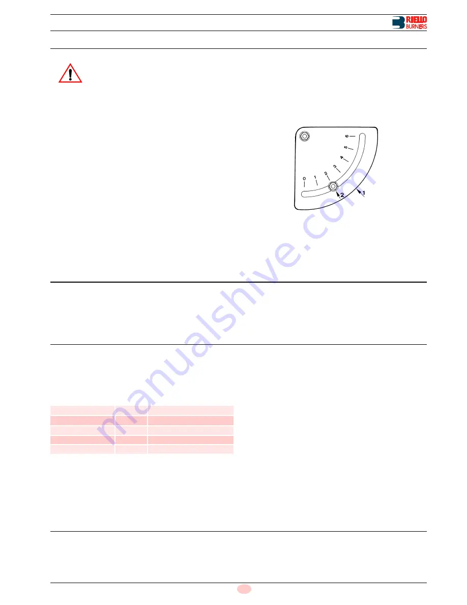
• Fan air gate valve
Adjust the fan air gate valve by using the indexed selector
1)(Fig. 28) after having loosened the nut 2).
NOTE:
Burner starting and operation phases are indicated in
page 29.
7.4
Combustion characteristics
The burner delivery
must not exceed the rated delivery for the
boiler, and should be adjusted in relation to the user's effective
heating requirements and selected within the firing rate (See
page 10).
A lower setting of the boiler provides for a lower flue gas fume
temperature, thus increasing combustion efficiency and saving
fuel.
7.5
Emissions into the atmosphere
Test boilers UNI-DIN
(Fig. 6 on page 12): emissions of Bachar-
ach-CO
2
-CO-CxHy-NOx obtained in laboratory tests with our
burners proved to be lower than the limits defined by EC Norms
EN 267 under the operating conditions established by these
standards, see (Tab. L).
Tab. L
Commercial boilers:
emissions of Bacharach-CO
2
-CO-CxHy-
NOx must not exceed the limits imposed by locally-applicable
regulations for burner installations. In particular, the CO
2
level
should not be higher than 13.5% in order to prevent variations in
the draught and air temperature or dirty burner conditions from
causing polluting combustion.
An insufficient CO
2
level must also be avoided, since, in addition
to raising costs and falling short of the established range, this can
also be the cause for the generation of a dangerous quantity of
uncombusted hydrocarbons in the flue gas (yellow Bacharach)
and the detachment of the flame upon ignition.
The combustion values measured may be considered reliable
only if there are no entries of air between the burner and the stack
flue gas sampling point. Check for penetration of outside air by
placing a column of smoke near the suspected leak in the seal: if
the smoke column is drawn towards the seal there must be an en-
try of air.
7.6
Flue gas temperature
This temperature varies in relation to the delivery generated: the
lower the delivery, the lower the temperature and the higher the
fuel saving.
Bear in mind that excessive temperature reduction, however,
gives rise to the formation of condensate.
WARNING
It is advisable to first set the burner for operating
on oil and then for gas.
Execute the fuel exchange when the burner is off.
Fig. 28
D412
EN 267 (5-91)
Bacharach
n°
< 1
CO
2
%
> 12.3
CO
ppm
< 100
CxHy
ppm
< 10
NOx
ppm
< 150
N.B.
Excess air %
= CO
2
max : CO
2
measured
CO
2
max
= 15,2%
Example
CO
2
measured
= 13,5%
Excess air
= 15,2 : 13,5 = 1,13 = 13%
Содержание PRESS GBV
Страница 2: ......
Страница 38: ......
Страница 39: ......
Страница 40: ...Subject to modifications RIELLO S p A I 37045 Legnago VR Tel 39 0442 630111 http www rielloburners com...


