


17
20013962
E
Funcionamiento
8.1
Notas sobre la seguridad para la primera puesta
en funcionamiento
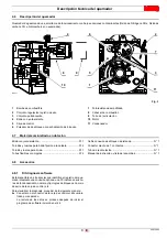
8.2
Regulación de la combustión
De acuerdo con la Directiva de Rendimiento 92/42/EEC la apli-
cación del quemador a la caldera, el ajuste y la prueba deben
realizarse siguiendo el manual de instrucciones de la caldera, in-
cluyendo el control de la concentración de CO y CO
2
en los ga-
ses de combustión, sus temperaturas y la temperatura media del
agua en la caldera. Según el caudal requerido por la caldera, se
debe determinar la boquilla, la presión de la bomba, la posición
del grupo difusor, la apertura de las ranuras de recirculación de
humos, la regulación del registro del aire, la regulación del cabe-
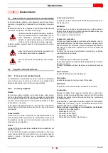
zal de combustión, ver la tabla que sigue.
Los valores indicados en la tabla se obtienen en una caldera
CEN (según EN267), y se refieren al 13% de CO
2
, al nivel del
mar (1013 hPA) y con temperatura ambiente y del gasóleo a
20°C, con presión en la cámara de combustión a 0 mbar.
Tab. A
8.3
Boquillas recomendadas
Steinen
tipo 60° H;
Danfoss
tipo 60° H;
Delavan
tipo 60° W.
El quemador está en conformidad con los requerimientos sobre
emisiones previstos por la norma EN 267.
Para garantizar la regularidad de las emisiones se deben utilizar
boquillas aconsejadas y/o alternativas indicadas por Riello en las
instrucciones y advertencias.
8
Funcionamiento
ATENCIÓN
La primera puesta en funcionamiento del quema-
dor debe ser realizada por personal habilitado se-
gún todo lo indicado en el presente manual y en
conformidad con las normas y disposiciones de
ley vigentes.
ATENCIÓN
Comprobar el correcto funcionamiento de los dis-
positivos de regulación, mando y seguridad.
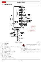
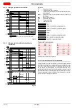
ATENCIÓN
El aire comburente llega aspirado desde el exte-
rior, por lo tanto pueden existir variaciones sensi-
bles de temperatura que pueden influir en el
porcentaje de CO
2
.
Se recomienda regular el CO
2
según el gráfico.
Ejemplo: si la temperatura del aire exterior es de
10 °C, regular el CO
2
a 12,5% (± 0,2%).
%
CO
2
Temperatura del aire exterior (°C)
14,5
14,0
13,5
13,0
12,5
12,0
11,5
0
5
10
15
20
25
30
35
40
D4604
Fig. 15
Boquilla
Presión
bomba
Caudal
quemador
Regulación cabezal de
combustión
Regulación
registro de aire
GPH
Ángulo
bar
kg/h ± 4%
Índice
Índice
1,00
60° H
12
3,8
1
1,5
1,10
60° H
12
4,3
1,5
2
1,25
60° H
12
4,9
2
3
1,35
60° H
12
5,2
2,5
3,5
1,50
60° H
12
6,0
4
5
ATENCIÓN
Para alcanzar las emisiones en CLASSE 3
(EN267:1999) se utilizan las boquillas con
cono vacío.
ATENCIÓN
Se aconseja sustituir anualmente las boquillas
durante el mantenimiento periódico.
PRECAUCIÓN
El uso de boquillas diferentes de las prescritas por
Riello S.p.A. y el mantenimiento periódico inco-
rrecto pueden implicar la inobservancia de los lí-
mites de emisión previstos por las normativas
vigentes y en casos extremos, el riesgo potencial
de daños a cosas o a personas.
La Sociedad fabricante no se responsabilizará de
ninguna manera por los daños causados debido a
la inobservancia de las prescripciones presentes
en este manual.
Содержание BGK3
Страница 2: ......
Страница 30: ......
Страница 58: ...20013962 Notes Notas...
Страница 59: ...20013962 Notes Notas...


