


20013962
8
GB
Technical description of the burner
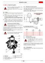
4.4
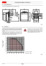
Overall dimensions
The burner and flange dimensions are indicated in Fig. 1.
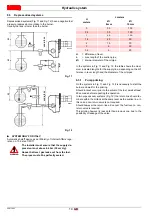
4.5
Firing rate
The burner delivery must be selected within area of the diagrams
(Fig. 2). This area is called firing rates and provides the maximum
delivery of the burner in relation to the pressure in the combustion
chamber.
The work point may be found by plotting a vertical line from the
desired delivery and a horizontal line from the pressure in the
combustion chamber. The intersection of these two lines is the
work point which must lie within the firing rates.
Fig. 1
230
11
4
5
°
4
5
°
ø 89
222
300
189
106
140
168
12
83
83
285
34
5
ø9
0
140
D7217
34
WARNING
The firing rate area values have been obtained
considering a surrounding temperature of 20 °C,
and an atmospheric pressure of 1013 mbar (ap-
prox. 100 m above sea level) and with the combu-
stion head adjusted as shown on Tab. A.
Fig. 2
Pressure in combustion
chambe
r –
mbar
Light oil output –
kg/h
Thermal power –
kW
4
5
6
- 0.4
- 0.2
0.0
0.2
0.4
0.6
0.8
1.0
1.2
1.4
1.6
1.8
45
50
55
60
65
70
75
40
D9487
Содержание BGK3
Страница 2: ......
Страница 30: ......
Страница 58: ...20013962 Notes Notas...
Страница 59: ...20013962 Notes Notas...