Riello AriaPRO 004 ME Скачать руководство пользователя страница 26

System’s drainage

-  Position the system’s main switch in the “off” position.
-  Check that the system’s charging tap is closed.
-  Open the water discharge tap outside the machine.

  Any antifreeze liquid contained in the system should not be discharged 

freely as it is a pollutant.

Ordinary maintenance

Preliminary instructions

 Regular maintenance is essential in order to keep the unit in top 

condition, and must be carried out at least once a year by the Technical 
Service or by skilled technicians.

 Plan the maintenance schedule according to the characteristics of 

installation and the use of the unit.

  For units installed in a seaside environment, the maintenance intervals 

shall be halved.

 After carrying out the necessary maintenance actions, the original 

conditions must be restored.

 Do not open the access covers and carry out technical or cleaning 

activities before disconnecting the unit from the power grid by 
positioning the system’s main switch in the “off” position.

Cleaning

 Do not open the access covers and carry out technical or cleaning 

activities before disconnecting the unit from the power grid by 
positioning the system’s main switch in the “off” position.

-  The only necessary cleaning activity to be carried out by the system’s 

user concerns the unit’s external cabinet, which must be cleaned using 
exclusively a cloth wet with soapy water.

-  In case of tough stains, wet the cloth with a mix of 50% water and 

denatured  alcohol or with specific detergents.

-  After washing, dry the surfaces carefully.

  Do not use sponges with scouring products or powdered detergents.

Operations

The annual maintenance plan includes the following checks:

 Mesh filter cleaning

 Supply voltage

 Fastening of electric connections

 Status of the hydraulic joints

 Water circuit charging

 Pump operation check

 Presence of air in the hydraulic circuit

 Safeties efficiency

 Compressor’s remote control switch status

 Plate heat exchanger’s resistor efficiency

 Compressor’s resistor efficiency

 Cleaning of fan grids

Preliminary instructions

  Check that the main power supply line is disconnected.
  Use tools appropriate for the refrigerant used.
  It is strongly suggested to use safety goggles and gloves.
  In case of partial leak of refrigerant gas, the circuit must be completely 

emptied before being recharged, and the refrigerant must be 
recovered.

 Any gas leaks indoors can generate toxic gases if they come into 

contact with naked flames or high temperature bodies, in case of 
leaks, please air the rooms thoroughly.

 Do not charge the refrigerating circuits with a different refrigerant from 

the prescribed one.

 Do not use oils that are different from the prescribed one. The use of 

different oils may seriously damage the compressor.

 Do not use oxygen or acetylene or other flammable or poisonous 

gases in the refrigerating circuit, as they can cause explosions.

 Operating conditions different from the nominal ones may yield values 

that differ considerably.

Compressor

The compressor is installed on the unit already charged with oil and 
sealed.

In case of breakages, if the compressor can be repaired, use only original 
ester oil. The oil used in the compressor is ESTER OIL VG74 (VG68 for 
the 12kW).

 Do not use oils that are different from the prescribed one. The use of 

different oils may seriously damage the compressor.

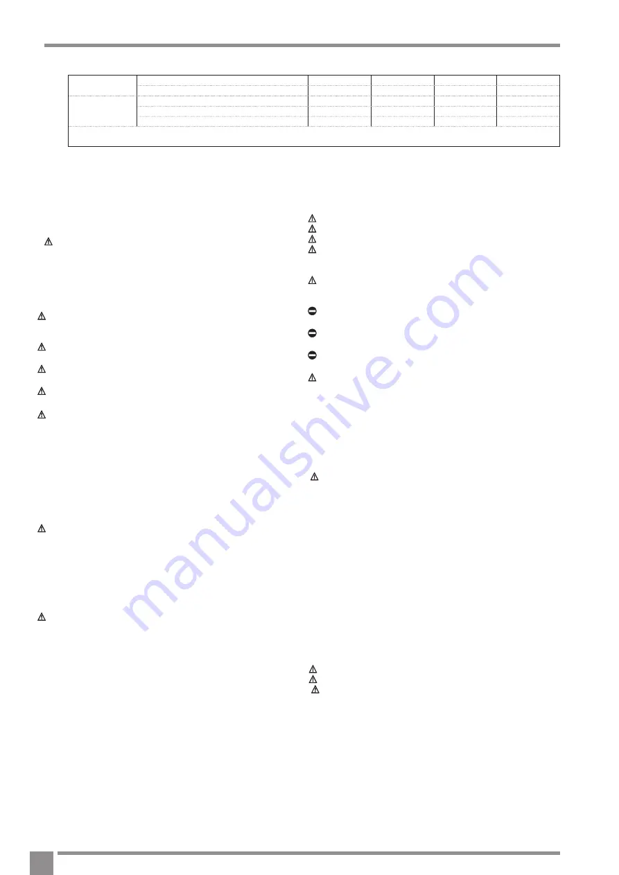
Extraordinary maintenance

% Inhibited ethylene glycol

10%

20%

30%

40%

Freezing temperature (*)

-4°C

-9°C

-15°C

-23°C

Correction factor

Capacity 

0,996

0,991

0,983

0,974

Input power

0,990

0,978

0,964

1,008

Pressure drop

1,003

1,010

1,020

1,033

(*) Note : the temperature values are approximate
Always refer to the temperature values indicated for the specific model

Refrigerant charge

Proceed as follows:


Empty and dry the whole refrigerating circuit using a vacuum pump 

connected to the low pressure port, until the value displayed on the 

vacuum gauge is about 10 Pa.


Wait for a few minutes and check that said value does not go up 

again.


Connect the refrigerant gas cylinder or a charging cylinder to the low 

pressure line port (the charge connection position can be seen on the 

refrigerant circuit diagram).


Charge the required quantity of refrigerant gas, as shown in the unit’s 

technical tag

In case of a partial leak, the circuit must be completely emptied before 
being recharged.

  The refrigerant must be charged into the unit only in its liquid state.
  Do not use refrigerants and lubricants different from those specified.

    Do not compress the air (Avoid the presence of air, caused by leaks, 

in the refrigerant circuit).


Always check the overheating and undercooling values which, in the unit’s 

nominal operating conditions, must fall between 5 and 10° C in the refri-

gerators and 4 and 8°C in the heat pumps, respectively.

Once the appliance has been serviced, the benchmark Service Record 
must be completed.
For UK only: It is important that the Benchmark Service Record is correctly 
completed and handed to the user. Failure to install and commission the 
appliance to the manufacturers instructions will invalidate the warranty.


 26

Содержание AriaPRO 004 ME

Страница 1: ...Installation Servicing Instructions THESEINSTRUCTIONS TOBERETAINED BYUSER Vok ra is a licensed member of the Benchmark scheme which aims to improve the standards of installation and commissioning of...

Страница 2: ...2...

Страница 3: ...maintenance operations please adopt the appropriate attire and accident prevention devices The Manufacturer waives all and any responsibility for failure to observe the safety and accident prevention...

Страница 4: ...onents Micro processor electronic control regulation performance Climate control The AriaPRO range units are designed for the production of refrigerated water for air conditioning heated water for hea...

Страница 5: ...1 58 1 96 3 46 4 42 EER 9 3 02 3 2 98 2 96 2 95 ESEER 9 4 36 4 51 4 15 4 22 4 31 Generalities Sound pressure in heating mode dB A 42 42 44 47 48 Sound pressure in cooling mode dB A 44 44 45 48 49 Com...

Страница 6: ...A Cold zone Low temperature 30 35 C s 133 120 110 115 133 SCOP 3 41 3 07 2 82 2 94 3 40 Pdesign 6 03 7 75 6 46 15 75 17 25 Annual consumption kW h 4 148 5 927 5 381 12 620 11 945 Warm zone Low tempera...

Страница 7: ...hot water production may be limited according to the settings of the safety devices in the equipment For technical activities please refer to the technical tag mounted on board the machine It is forbi...

Страница 8: ...mm 356 640 G mm 466 750 H mm 40 44 L mm 60 69 A Flow rate l s B Available static pressure kPa 0 1 0 0 75 65 B A 4 6 55 45 35 25 15 5 75 65 B 55 45 35 25 15 5 0 2 0 3 0 4 0 5 0 1 0 0 A 0 2 0 3 0 4 0 5...

Страница 9: ...s and defrost OAT Outside air probe LF Frequency Limiting IS Domestic water input SV Three way domestic water valve Y Yellow O Orange R Red G Grey A Brown C Black V Violet B Blue W White Y G Yellow Gr...

Страница 10: ...3 J16 J5 2 J16 4 EHTR WP J5 3 J5 J16 5 J5 4 J16 6 J5 5 21CF 7 6 5 4 3 2 1 J20 7 REMOTE J20 6 1FS 1 2 22CF 1 2 1 J15 1 J20 5 J15 J17 1 J17 2 J10 1 J20 4 J20 1 J10 2 J20 3 J17 J10 3 J20 2 J10 1OAT J10 4...

Страница 11: ...P20 P35 P34 P19 P18 P04 P05 P06 1P C BOARD P11 P08 1MCC1530 3CF 1 2 3 4CF 1 2 3 CN805 1 1 P33 2R P32 5CF 2 1 4CM 2 1 P31 2 10 J4 1 P30 CN701 2 03 J3 1 6CF 1 2 3 1 2 08 J1 1 1RV F7 P03 P10 P02 CN806 1...

Страница 12: ...3 J16 J5 2 J16 4 EHTR WP J5 3 J5 J16 5 J5 4 J16 6 J5 5 21CF 7 6 5 4 3 2 1 J20 7 REMOTE J20 6 1FS 1 2 22CF 1 2 1 J15 1 J20 5 J15 J17 1 J17 2 J10 1 J20 4 J20 1 J10 2 J20 3 J17 J10 3 J20 2 J10 1OAT J10 4...

Страница 13: ...P35 P34 P19 P18 P04 P05 P06 1P C BOARD P11 P08 1MCC1530 42CF 1 2 3 43CF 1 2 3 CN805 1 1 P33 P32 2R 44CF 2 1 9CM 2 1 P31 P30 CN701 45CF 1 2 3 1 1RV F7 P03 1F 1 2 P10 P02 CN806 1 CN300 CN700 CN503 CN502...

Страница 14: ...HUMIDITY J5 1 J16 3 J16 J5 2 J16 4 EHTR WP 12 J5 3 J5 J16 5 J5 4 EHS DFR J16 6 4 J5 5 60CF 7 6 5 4 3 2 1 J20 7 ALARM 5 J20 6 1FS 1 2 61CF 1 2 1 J15 1 J20 5 J15 J17 1 J17 2 16 J10 1 J20 4 J20 1 J10 2 J...

Страница 15: ...2CM 1 2 3 7CF 1 2 3 P12 N P13 R 1 8CF 1 2 9CF 1 2 1 CN05 CN04 3 P21 10CF 1 2 3 1 CN303 P24 1 11CF 1 2 3 4 5 12CF 1 2 3 4 5 1 1FM CN800 CN06 P28 J4 1 2 10 J3 1 2 03 J1 1 2 08 P29 13CF 1 2 3 4 5 ED 1 CN...

Страница 16: ...UMIDITY J5 1 J16 3 J16 J5 2 J16 4 EHTR WP 12 J5 3 J5 J16 5 J5 4 EHS DFR J16 6 4 J5 5 32CF 7 6 5 4 3 2 1 J20 7 ALARM 5 J20 6 1FS 1 2 33CF 1 2 1 J15 1 J20 5 J15 J17 1 J17 2 16 J10 1 J20 4 J20 1 J10 2 J2...

Страница 17: ...00 WHITE CN710 WHITE SW802 SW804 SW803 ON ON ON 4 3 2 1 4 3 2 1 4 3 2 1 SW801 CN704 BLUE SW800 RY704 P04 CN701 WHITE P05 CONTROL P C BOARD MCC1571 P06 CN04 WHITE P07 CN200 F03 T10A 250V F01 T25A 250V...

Страница 18: ...HUMIDITY J5 1 J16 3 J16 J5 2 J16 4 EHTR WP 12 J5 3 J5 J16 5 J5 4 EHS DFR J16 6 4 J5 5 84CF 7 6 5 4 3 2 1 J20 7 ALARM 5 J20 6 1FS 1 2 85CF 1 2 1 J15 1 J20 5 J15 J17 1 J17 2 16 J10 1 J20 4 J20 1 J10 2 J...

Страница 19: ...ortation The unit must be handled by skilled technicians appropriately equipped and with the appropriate tools to manage the unit s weight in compliance with the accident prevention regulations When h...

Страница 20: ...units must Be placed on a level surface able to support their weight Be placed on a sufficiently rigid floor slab that does not transfer vibrations to the rooms below or next door It is suggested to...

Страница 21: ...so that the pipes can be washed without having to disconnect the unit The connection pipes should be of a suitable diameter and suppor ted so that their weight does not rest on the appliance It is ma...

Страница 22: ...e connection points in the pre cut part Remove the pre cut part Remove the hole s cutting edges Insert the supplied cable protections Only for size 015 use the strain relief supplied with the unit Thr...

Страница 23: ...C B D C 004 006 008 D C A E 012 015 Legend A Position 4 Led Inverter diagnostics board 12ME 15ME B LED GMC position Diagnostic board C Installation terminal strip D Cable holder E Strain relief 23...

Страница 24: ...d the connection cable of the control panel through the hole in the base Anchor the base with appropriate screws and bolts Connect the cable to the clamps on the control panel paying attention to pola...

Страница 25: ...charge Operations After deactivating the unit Position the remote switch in the off position Position the system s main switch in the off position Deactivate the indoor terminal units by positioning t...

Страница 26: ...ed flames or high temperature bodies in case of leaks please air the rooms thoroughly Do not charge the refrigerating circuits with a different refrigerant from the prescribed one Do not use oils that...

Страница 27: ...START TIME Activates the programming menu displaying the beginning of the six periods of time scheduled PERIOD Activates the programming menu displaying the six periods of time scheduled DAYS Activate...

Страница 28: ...meter Activate the arrow keys Set the current value Push the OK key to confirm Setting of room temperature Push the mode key Select the desired operation mode Activate the arrow keys Set the desired t...

Страница 29: ...change of the next parameter shall be enabled To move Activate the arrow keys To confirm Push the OK key to confirm Refer to the functions table for further details on the various parameters Quick key...

Страница 30: ...5 10 15 20 15 20 25 30 35 40 45 par 4 1 2 3 4 15 25 35 45 55 65 15 10 5 0 5 10 15 20 25 par 4 1 2 3 4 1 MAX W T W1 Par No 121 2 NO HEAT T W1 Par No 120 3 REGION T O Par No 118 4 STOP H T O Par No 119...

Страница 31: ...s Before resetting it is necessary to remove the cause of the anomaly Abnormal operations are notified by the Control Panel with numeric codes Part of the alarms resets automatically while others requ...

Страница 32: ...etc Discharge temp error Power supply error Heat sink overheat error Gas leak detection 4 way valve reverse error High pressure protective operation Fan system error Driving element short circuit Pos...

Страница 33: ...rature 11 Lock Outdoor Temperature measured by the sensor C 30 C 90 C Outdoor temperature GMC 12 Lock Outdoor temperature read by the GMC board C 20 C 65 C Room sensor temperature adjustment 13 Correc...

Страница 34: ...d for ACS when External Air Temperature tem perature set with code 148 2 Humidity control 1 2 2 Frost Delta set point 109 Code used to set the frost set point delta used by the antifreeze system as pe...

Страница 35: ...3 Heating 4 Faulty 5 Defrost Lock Compressor max frequency 132 The code indicates the maximum frequency of the compressor calculated by the GMC control board Lock Requested frequency 133 The code ind...

Страница 36: ...0 Always active 1 On Off depending by actual room temperature vs room temperature set point same hysteresis of the thermostat function If the command is not installed or the room sensor is unavailabl...

Страница 37: ...s The manufacturer s literature including Benchmark Checklist and Service Record has been explained and left with the customer Yes CENTRAL HEATING MODE Heating Flow Temperature C Heating Return Temper...

Страница 38: ...ature Date Engineer Name Company Name Telephone No Operative ID No Comments Signature Date Engineer Name Company Name Telephone No Operative ID No Comments Signature Date Engineer Name Company Name Te...

Страница 39: ......

Страница 40: ...ra co uk www vokera co uk www vokera ie Sales General Enquires T 0844 391 0999 F 0844 391 0998 Vok ra Ireland West Court Callan Co Kilkenny T 056 7755057 F 056 7755060 Vok ra Limited reserve the right...

Отзывы: