19
APPENDIX
Electrical wiring
NOTES
Electrical wiring must be made in accordance with
the regulations currently in force in the country of
destination and by qualified personnel.
The Manufacturer declines all liability for modifica-
tions or connections other than those shown on
these diagrams.
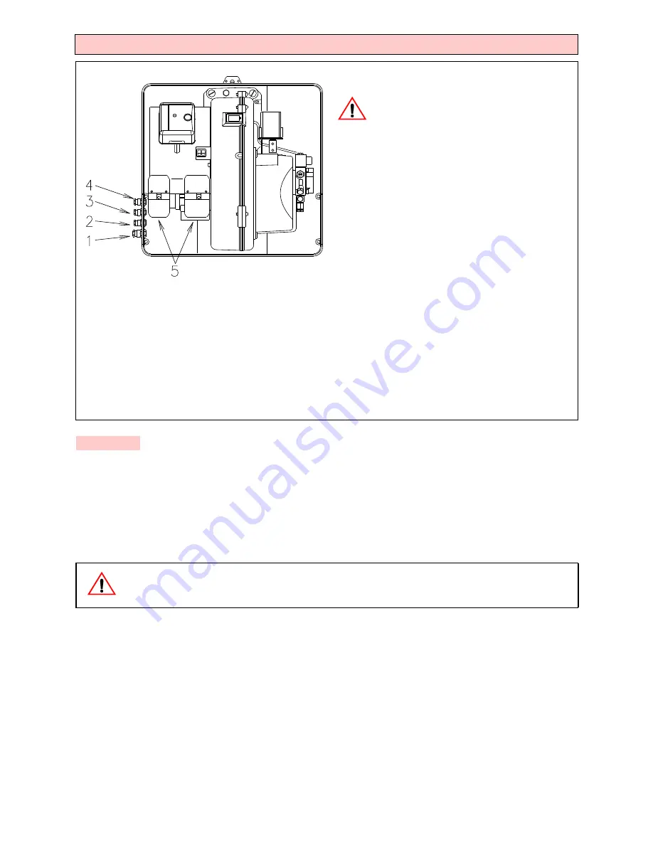
All the cables to be connected to the burner are fed
through the grommets.
Use flexible cables according to regulation EN 60
335-1:
•if in PVC boot, use at least H05 VV-F;
•if in rubber boot, use at least H05 RR-F.
All the cables to be connected to the burner sockets 4)(A) must be
routed through the fairleads, supplied by the manufacturer for in-
sertion into the holes in the plate, preferably those on the left side,
after having removed the thin diaphragm effectively closing the ap-
erture.
1 - Pg 11 Single-phase power supply
2 - Pg 9
Control device TL
3 - Pg 9Control device TR
Cable section not indicated: 1.5 mm
2
.
• The burner is factory set for two-stage operation and it must therefore be connected to the TR remove control device to command light oil
valve VH/L.
Alternatively, if single stage operation is required, instead of control device TR install a jumper lead between terminals T6 and T8 of connector
X4.
• The burners have been type- approved for intermittent operation. This means they should compulsorily be stopped at least once every 24
hours to enable the control box to perform checks of its own efficiency at start-up. Burner halts are normally provided for automatically by the
boiler load control system.
.
ATTENTION:
- Do not invert the neutral with the phase wire in the electricity supply line. Any inversion would cause a lockout due
to firing failure.
- Only use original spare parts to replace the components.
NOTE
D10324


