


20163413
30
GB
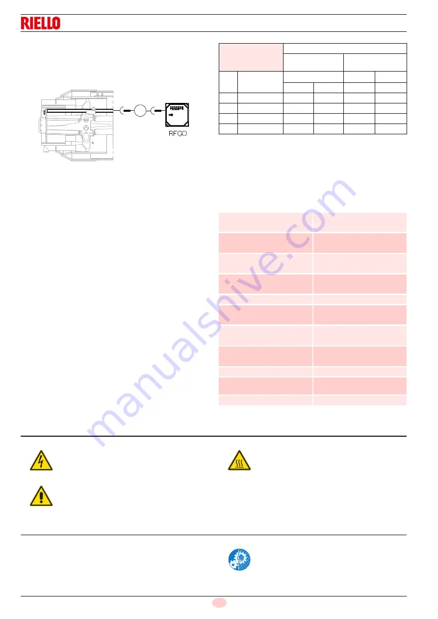
Flame presence check
Check the level of the flame detection signal with the “Check
mode” function from the flame control: the LEDs from 2 to 6
indicate the flame signal level, respectively. See “LED indicator
and special function” on page 31.
Check Mode
With burner flame on:
hold the reset button on the flame control pressed for at
least 3 sec.;
the button colour will change from green to yellow;
each operating status signalling LED will be compared to
20% of the maximum brightness;
press the reset button again (<0.5sec) to reset the standard
operation of the signalling LEDs.Boiler
Clean the boiler as indicated in its accompanying instructions in
order to maintain all the original combustion characteristics in-
tact, especially the flue gas temperature and combustion cham-
ber pressure.
Gas leaks
Make sure that there are no gas leaks on the pipes between the
gas meter and the burner.
Gas filter
Replace the gas filter when it is dirty.
Combustion
If the combustion values measured before starting maintenance
do not comply with applicable legislation or do not indicate effi-
cient combustion, consult the Tab. K or contact our Technical
Support Service to implement the necessary adjustments.
It is advisable to set the burner according to the type of gas used
and following the indications in Tab. K.
Tab. K
7.2.4
Safety components
The safety components should be replaced at the end of their life
cycle indicated in the Tab. L.
The specified life cycles do not refer to the warranty terms indi-
cated in the delivery or payment conditions.
Tab. L
7.3
Opening the burner
See “Access to head internal part” on page 18.
7.4
Closing the burner
Refit following the steps described but in reverse order; refit all
burner components as they were originally assembled.
-
μ A
+
Fig. 37
20156526
EN 676
Air excess
Max. output
1.2
Min. output
1.3
GAS
CO
2
theoretic
al max. 0% O
2
CO
2
% Calibration
CO
NO
X
= 1.2
= 1.3
mg/kWh mg/kWh
G 20
11.7
9.7
9.0
100
170
G 25
11.5
9.5
8.8
100
170
G 30
14.0
11.6
10.7
100
230
G 31
13.7
11.4
10.5
100
230
Safety component
Life cycle
Flame control
10 years or 250.000
operation cycles
Flame sensor
10 years or 250.000
operation cycles
Gas valves (solenoid)
10 years or 250.000
operation cycles
Pressure switches
10 years or 250.000
operation cycles
Pressure adjuster
15 years
Servomotor (electronic cam)
10 years or 250.000
operation cycles
Oil valve (solenoid)
10 years or 250.000
operation cycles
Oil regulator
10 years or 250.000
operation cycles
Pipes/ oil fittings (metallic)
10 years
Flexible hoses (if present)
5 years or 30.000
pressurised cycles
Fan impeller
10 years or 500.000 start-ups
DANGER
Disconnect the electrical supply from the burner
by means of the main system switch.
DANGER
Close the fuel interception tap.
Wait for the components in contact with heat
sources to cool down completely.
Carry out all maintenance work and mount the
casing again.
Содержание 20155875
Страница 2: ...Translation of the original instructions...
Страница 43: ...41 20163413 GB Appendix Electrical panel layout...
Страница 44: ...20163413 42 GB Appendix Electrical panel layout 0 0 1 0 1 2 0 3 0 1 0 1 1 0 0 0 0 0 40 4 4 0 0 1 2 0 1...
Страница 45: ...43 20163413 GB Appendix Electrical panel layout 0...
Страница 47: ...45 20163413 GB Appendix Electrical panel layout 0 0 1 2 2 2 2 2 2 2 0 0 2 0 2 0 1 2...
Страница 48: ...20163413 46 GB Appendix Electrical panel layout 0 1 2 1 3 4 56 4 6 4 6 5 4 786 9 3 1 2 78 0 0 2 2 2...


