


22
START CONDENS 25 IS
Twin pipes ø 80 with ducting Ø 50, Ø 60 and Ø 80
Thanks to the boiler characteristics, a flue gas discharge pipe ø
80 can be connected to the ducting ranges ø 50, ø 60 and ø 80.
9
For the ducting, you are advised to make a project calculation in
order to respect the relevant standards in force.
The table shows the standard configurations allowed.
T
able of standard pipe configurations
(*)
Air suction
1 bend - 90° ø 80
4.5 m pipe ø 80
Flue gas discharge
1 bend - 90° ø 80
4.5 m pipe ø 80
Reduction from ø 80 to ø 50 or from ø 80 to ø 60
90° stack base bend ø 50 or ø 60 or ø 80
For ducting pipe lengths see table
(*) Use flue gas system accessories in plastic (PP) for condensing
boilers: Ø50 and Ø80 H1 class and Ø60 P1 class.
The boilers are factory set to:
25 IS:
4.900 rpm (CH), 6.100 rpm (DHW) and the maximum length
that can be reached is 7 m for the ø 50 pipe, 25 m for the ø 60 pipe
and 75 m for the ø 80 pipe.
Should it be necessary to achieve greater lengths, compensate the
pressure drop with an increase in the r.p.m.of the fan, as shown in
the adjustments table, to ensure the rated heat input.
9
The minimum calibration is not modified.
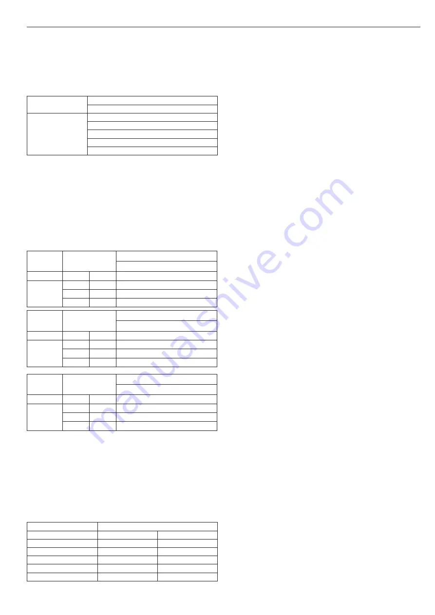
Adjustments table
Fan rotations
r.p.m.
Pipes Ø 50 (*)
max length (m)
CH
DHW
25 IS
4.900
6.100
7
5.000
6.200
9
5.100
6.300
12 (**)
Fan rotations
r.p.m.
Pipes Ø 60 (*)
max length (m)
CH
DHW
25 IS
4.900
6.100
25
5.000
6.200
30
5.100
6.300
38 (**)
Fan rotations
r.p.m.
Pipes Ø 80 (*)
max length (m)
CH
DHW
25 IS
4.900
6.100
75
5.000
6.200
90
5.100
6.300
113 (**)
(*) Use flue gas system accessories in plastic (PP) for condensing
boilers.
(**) Maximum installable length ONLY with exhaust pipes in H1
class.
The configurations Ø 50, Ø 60 and Ø 80 show test data verified in
the laboratory.
In the case of installations that differ from those indicated in the
“standard configuration” and “adjustments” tables, refer to the
equivalent linear lengths below.
9
In any case, the maximum lengths declared in the booklet are
guaranteed, and it is essential not to exceed them.
COMPONENT
Linear equivalent in metres Ø80 (m)
Ø 50
Ø 60
Bend 45°
12,3
5
Bend 90°
19,6
8
Extension 0.5m
6,1
2,5
Extension 1.0m
13,5
5,5
Extension 2.0m
29,5
12
2.11 - System loading and emptying
Once the hydraulic connections have been carried out, fill the
system.
Loading
• Open by two or three turns the plugs of the lower (A - Fig. 13) and
upper (D - Fig. 13) automatic air vent valves; to allow a continuous
venting of the air, leave the plugs of valves A and D open (Fig. 13).
• Make sure the cold water inlet tap is open, turning it anti-clock-
wise.
• Open the filling tap (outside the boiler) until the pressure indicated
by the water pressure gauge is between 1 and 1.5 bar.
• Close the filling tap.
NOTE -
The venting of the
START CONDENS IS
boiler takes place
automatically via the two automatic vent valves A and D (Fig. 13),
the first positioned on the circulator and the second inside the air
distribution box.
NOTE -
If the venting phase proves difficult, proceed as described
in the paragraph "Eliminating the air from the heating circuit and
boiler".
Emptying
• Before starting emptying, switch off the electrical supply by turning
off the system's main switch
• Close the cold water inlet tap
• Close the shut-off devices of the heating system
• Manually loosen the system drain valve (B - fig. 13)
Eliminating the air from the heating circuit and boiler (fig. 14)
During the initial installation phase, or in the event of extraordinary
maintenance, you are advised to perform the following sequence of
operations:
• Open the lower automatic air vent valve cap (A - fig. 13) and leave
it open.
• Turn on the system filling tap
• Switch on the electricity supply to the boiler, leaving the gas tap
turned off.
• Activate a heat request via the ambient thermostat or the remote
control panel, so that the 3-way valve goes into heating mode.
• Activate a DHW request by open a tap for 30" per minute so that
the three-way valve cycles from heating to DHW and vice versa
for about ten times (in this situation, the boiler will go into alarm
due to lack of gas, therefore reset it whenever this is proposed).
• Continue the sequence until no more air is felt coming from the
air vent valve.
• Check the system pressure level is correct (the ideal level is 1
bar).
• Turn off the system filling tap.
• Turn on the gas tap and ignite the boiler.
2.12 - First commissioning preparation
Before the ignition and the functional testing of the
START CONDENS IS
boiler, it is necessary to:
• check that the system's fuel and water supply taps are open (fig. 15)
• check that the gas type and the power supply pressure are those
for which the boiler is designed
• make sure the cap on the vent valve is open
• check on the display that the pressure of the water circuit when
cold is between 1 bar and 1.5 bar and that the circuit is vented
• Check that the pre-loading of the expansion tank is adequate (see
the Technical data table)
• check that the electrical connections have been carried out cor-
rectly
• check that the combustion product outlet and air suction pipes
were adequately realised
• check that the circulator rotates freely because, especially after
long periods of non-operation, deposits and/or debris can prevent
free rotation.
9
Before loosening or removing the closing tap of the circulator,
protect the underlying electrical devices from possible water
leakage.