background image

I

F

E

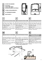
Prima di passare all'installazione si consiglia di
effettuare le seguenti veriche:
1. La struttura del cancello deve essere solida

ed appropriata;

2. Leggere attentamente le istruzioni.
3. Accertarsi che il cancello, durante tutto il suo

movimento, non subisca punti d'attrito e che
non vi sia pericolo di deragliamento.

4. Prevedere un fermo anta in apertura e uno in

chiusura ed il percorso dei cavi elettrici come
da impianto tipo.

Avant de passer à l'installation, il est conseillé
d'effectuer les vérications préliminaires
suivantes :
1. La structure du portail doit être solide et

appropriéè;

2. Lire attentivement les instructions.
3. S'assurer que la grille n'ait pas de points de

frottement durant tout le mouvement et qu'il
n'y a pas de danger de déraillement.

4. Prévoir le passage des câbles électriques

selon les dispositifs de commande et de
sécurité.

Antes de pasar a la instalación se aconseja
realizae los siguientes controles :
1. La estructura de al cancela debe ser sólida y

adecuada;

2. Leer atentamente las instruciones.
3. Comprobar que la cancela, durante todo su

movimiento, no presente puntos de roce y que
no exista peligro de descarrilamiento.

4. Disponer un conducto para apertura los

cables eléctricos que cumpla con la
disposiciones de mando y seguridad.

VERIFICHE PRELIMINARI

VERIFICATIONS PRELIMINAIRES

CONTROLES PRELIMINARES

I

F

E

1.

Linea di alimentazione

2.

Interrutore generale

3.

Interrutore differenziale

4.

Staffa di ne corsa

5.

Ace fast

6.

Fotocellula

7.

Cremagliera

8.

Costola sensibile

9.

Selettore a chiave o tastiera digitale

10. Lampeggiatore
11. Antenna

1.

Ligne d'alimentation

2.

Interrupteur général

3.

Interrupteur différentiel

4.

Etrier de n de course

6.

Photocellule

7.

Crémaillère

8.

Tranche de sécurité

9.

Sélécteur à clé et clasvier digital

10. Clignotant
11. Antenne

1.

Línea de alimentación

2.

Interruptor general

3.

Interruptor diferencial

4.

Aletas de tope

6.

Fotocélula

7.

Cremallera

8.

Nervio sensibile

9.

Selector de llave o teclado digital

10. Intermitente

QUADRO D'INSIEME

TABLEAU D'ENSEMBLE

CUADRO DE CONJUNTO

11. Antena

2

5.

Ace fast

5.

Ace fast

Содержание CARDIN ACE FAST

Страница 1: ...TRUCCIONES EL PRESENTE FOLLETO ESTÁ DESTINADO AL PERSONAL TECNICO ESPECIALIZADO EN INSTALACIONES ELECTROMECHANICAL GEARMOTORS FOR SLIDING GATES INSTRUCTION HANDBOOK THIS HANDBOOK IS INTENDED FOR QUALIFIED TECHNICAL INSTALLERS ELEKTROMECHANISCHER GESCHMIERTER GETRIEBEMOTOR FÜR SCHIEBETORE BEDIENUNGANWEISUNGEN DAS VORLIEGENDE HANDBUCH IST FÜR DAS MIT DER INSTALLATION BETRAUTE TECHNISCH QUALIFIZIERTE...

Страница 2: ...iguientescontroles 1 La estructura de al cancela debe ser sólida y adecuada 2 Leeratentamentelasinstruciones 3 Comprobar que la cancela durante todo su movimiento nopresente puntosderocey que noexistapeligrodedescarrilamiento 4 Disponer un conducto para apertura los cables eléctricos que cumpla con la disposicionesdemandoyseguridad VERIFICHE PRELIMINARI VERIFICATIONS PRELIMINAIRES CONTROLES PRELIM...

Страница 3: ...trolesteverrichten 1 Het frame van de poort moet stevig en geschiktzijn 2 Leesdeaanwijzingenaandachtig 3 Controleer of er tijdens de hele beweging van de poort geen wrijvingspunten zijn en of er geengevaarvanontsporingis 4 Breng een vleugelstop tijdens de opening en een vleugelstop tijdens de sluiting aan en leg de elektrische kabels aan zoals vermeld bij de standaardinstallatie PRELIMINARY CHECKS...

Страница 4: ...ische motorreductor met blokkering voor poorten meteenmax gewichtvan 00kg Éénfasevoedingvan230Vac RondselmetverticaletandheugelM4 I n c l u s i e f b e v e s t i g i n g s p l a a t e n bevestigingsschroeven Motorvoedingvan 24Vdc MODELS AND CHARACTERISTICS MODELLE UND EIGENSCHAFTEN MODELLEN EN SPECIFICATIES TECHNICAL DATA TECHISCHE DATEN U M Ace fast TECHNISCHE GEGEVENS 230 4 24 1 1 44 20 55 Alime...

Страница 5: ...g 1 e Fig 2 Importante FISSAGGIO PIASTRA DI BASE FIXATION PLAQUE DE BASE FIJACIÓN DE LA PLACA DE BASE GB D NL Observing the overall dimensions x the base plate to the ground by means of 4 strong rawl plugs or bury the counterplate in theconcrete Plan for one more sheating for the passage of thepowerlines Fig 1 Introduce screws A before xing the plate to the concrete in order for the gearmotortobe ...

Страница 6: ...ancela a mano hasta que advierta un chasquido en los engranajes Torelease thegearmotor raise thepanel g 3 insert the key and turn it completely clockwise until a click is heard This detaches the gate to enable free movement To lock the gearmotor turn the key completely anti clockwise until it locks in place Slowly move the gate until you hear the gear click and engage Um den Antrieb zu entriegeln ...

Страница 7: ...CIÓN DEL MOTORREDUCTOR GB D NL Removethecoverunscrewingthescrews g 4 Position the gearmotor on the baseplate and tightenthenutsonthetwoscrews Before tightening the two nuts fully down you can adjust the distance of the motor from the rack bymeansofthescrewsshowninFig 6 NowtightenthetwoM12 nutsfully down Fig 5 making sure that the gearmotor is rmly anchored to the ground throughout the range of gat...

Страница 8: ...utiliser un élément de crémaillère comme appui et point de référence a n de pouvoir positionner correctement les autres éléments et de garantir leur alignement g 10 Assurer toujours un jeu d 1 mm entre la crémaillère et le pignon de façon à ce que le poids du portail ne repose pas sur le pignon du motoréducteur g 9 Si le portail est neuf contrôler quelque temps après l installation le jeu entre pi...

Страница 9: ... Au ageundReferenzzuverwenden abb 10 Sicherstellen daß zwischen Zahnstange und Kolben ein Zwischenraum von 1 mm besteht so daß das Gewicht des Tors den Kolben des Getriebemotorsnichtbelastet abb 9 Bei neuen Toren in der Zeit nach der Installation das Spiel zwischen Zahnstange und Kolben überprüfen falls notwendig die Löcher der Zahnstange betätigen um das Spiel Zahnstange Kolben einzustellen Hinwe...

Страница 10: ...tvisiblefromtheoutside Position the brackets with magnets M and make sure that each bracket is suf ciently close to the electronic limit switch S to as to ensure the motor is stopped There must be a gap of between 2 and 8 mm between magnet M and limitswitch S Manually open the gate without it touching the mechanical stop and then x the limit switch bracket using the grub screws Fig Abb 8 so that p...

Страница 11: ...12V 1 2A back up batteries which when connected to the electronic control unit will provide suf cient power to open and close the gate for a limited time in the case of a mains powerfailure Fig Abb 11 Einbau von zwei 12V 1 2Ah Pufferbatterien die wenn korrekt mit der elektronischen Steuerung verbunden das Öffnen und Schließen des Tors bei Stromausfall für eine bestimmte Zeit garantierenkönnen Abb ...

Страница 12: ...es 4 S assurerquelemotoréducteurestalimenté 1 Véri er que le pignon denté soit en prise avec lacrémaillère 2 Contrôlerquele motoréducteurnesoitpas en position manuelle débloqué Contrôler que le motoréducteur ne soit pas bloqué par un des deux arrêts mécaniques Dans ce cas là débloquer manuellement le moteur et actionner le portail à la main en le libérant de ce fait de cette position anormale Plac...

Страница 13: ...te Kolben in die Zahnstangegreift 2 Kontrollieren daß sich der Getriebemotor in der manuellen Stellung deblockiert be ndet Kontrollieren daß der Getriebemotor nicht von einer der beiden mechanischen Verriegelungen blockiert ist In diesem Fall den Motor manuell deblokieren und das Tor per Hand betätigen und aus dieser anomalen Position befreien Danach die Bügel der Endschalter korrekt positionieren...

Страница 14: ... sur l automation l étiquette ou la plaque CE où sont indiqués les dangers présentés par l automation ainsi que les données d identi cation de la machine 9 Remettre à l utilisateur nal le mode d emploi les avertissements concernant la sécurité et la déclaration CE de conformité 10 S assurerquel utilisateura biencomprislefonctionnement automatique manuel et d urgence de l automation 11 Informer l u...

Страница 15: ...erheitshinweise und die EU Konformitätserklärung aushändigen 10 Sicherstellen dassderBedienerdiekorrekteautomatische und manuelle Funktionsweise sowie den Notbetrieb der Automatisierung verstanden hat 11 Den Benutzer schriftlich z B in den Bedienungsanleitungen über folgendes informieren a eventuelles Vorhandensein nicht geschützter Restrisiken vorhersehbarer unsachgemäßer Gebrauch b Vorschrift di...

Страница 16: ... riciclaggio o smaltimento del prodotto attenendosi alle norme di legge vigenti a livello locale SMALTIMENTO Ce produit est constitué de divers composants quipourraientàleurtourcontenirdessubstances polluantes Ne pas laisser ce produit gagner l environnement S informer sur le système de recyclage ou d élimination du produit conformément aux dispositions légales en vigueur à unniveau local ELIMINAT...

Страница 17: ...NOTE ...

Страница 18: ...NOTE ...

Страница 19: ......

Страница 20: ......

Отзывы: