background image

29

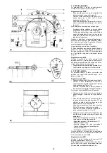
EINSTELLUNGEN VOR DER ZÜNDUNG

-

Handbetätigte Ventile vor der Gasarmatur
öffnen.

-

Den Gas-Minimaldruckwächter auf den Ska-
lenanfangswert (A) einstellen.

-

Den Gas-Höchstdruckwächter auf den Ska-
lenendwert (B) einstellen.

-

Den Luft-Druckwächter auf den Skalenan-
fangswert (C) einstellen.

-

Die Luft aus der Gasleitung entlüften.
Es wird empfohlen, die abgelassene Luft
über einen Kunststoffschlauch ins Freie
abzuführen, bis der Gasgeruch wahrnehm-
bar ist.

-

Ein U-Manometer (D) auf den Gasanschluß
an der Muffe einbauen. 
Hiermit wird die ungefähre Höchstleistung
des Brenners anhand des Diagramms auf
Seite 14 ermittelt.

-

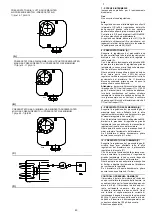
Parallel zu den beiden Gas-Magnetventilen
VR und VS zwei Glühbirnen oder einen
Tester anschließen, um den Zeitpunkt der
Spannungszufuhr zu überprüfen. 
Dieses Verfahren ist nicht notwendig, falls
die beiden Magnetventile mit einer Kontroll-
lampe ausgestattet sind, die die Elektrospan-
nung anzeigt.

-

Die Position der Gasdrossel, die bei Bren-
nerstillstand auf "geschlossen" steht (Zeiger
auf 0°), nicht verändern.

-

Flammkopf- und Luftklappenposition nicht
ändern.

Vor dem Zünden des Brenners sind die Gasar-
maturen so einzustellen, daß die Zündung unter
Bedingungen höchster Sicherheit bei einem ger-
ingen Gasdurchsatz erfolgt.

ANFAHREN DES BRENNERS

Die Fernsteuerungen schließen. 
Sobald der Brenner anfährt, den Drehsinn des
Motors kontrollieren.  
Kontrollieren, daß an den an die Magnetventile
angeschlossenen Kontrollampen und Span-
nungsmessern, oder an den Kontrollampen auf
den Magnetventilen, keine Spannung anliegt.
Wenn Spannung vorhanden ist, 

sofort

 den

Brenner ausschalten und die Elektroanschlüsse
überprüfen.

ZÜNDUNG DES BRENNERS

Wenn alle vorab angeführten Anleitungen
beachtet worden sind, müßte der Brenner
anfahren. 
Wenn hingegen der Motor läuft, aber die
Flamme nicht erscheint und eine Geräte-Störab-
schaltung erfolgt, entriegeln und das Anfahren
wiederholen. 
Sollte die Zündung immer noch nicht stattfinden,
könnte dies davon abhängen, daß das Gas
nicht innerhalb der vorbestimmten Sicherheit-
szeit von 3 s den Flammkopf erreicht. 
In diesem Fall den Gasdurchsatz bei Zündung
erhöhen. 
Das U-Rohr-Manometer (D) zeigt den Gase-
intritt an der Muffe an.  
Nach erfolgter Zündung den Brenner vollständig
einstellen.

ADJUSTMENTS BEFORE FIRST FIRING

-

Open manual valves up-line from the gas train.

-

Adjust the minimum gas pressure switch to
the start of the scale (A).

-

Adjust the maximum gas pressure switch to
the start of the scale (B).

-

Adjust the air pressure switch to the zero
position of the scale (C).

-

Purge the air from the gas line.
Continue to purge the air (we recommend
using a plastic tube routed outside the build-
ing) until gas is smelt.

-

Fit a U-type manometer (D) to the gas pres-
sure test point on the sleeve.
The manometer readings are used to calcu-
late MAX. burner power using the graph on
page 14.

-

Connect two lamps or testers to the two gas
line solenoid valves VR and VS to check the
exact moment at which voltage is supplied.
This operation is unnecessary if each of the
two solenoid valves is equipped with a pilot
light that signals voltage passing through.

-

Do not change the gas butterfly, which must
be closed (indicator to 0°) when the burner is
OFF.

-

Do not change the settings of the air gate
valve and the combustion head.

Before starting up the burner it is good practice
to adjust the gas train so that ignition takes
place in conditions of maximum safety, i.e. with
gas delivery at the minimum.

BURNER STARTING

Close the remote control devices. 
As soon as the burner starts check the direction
of rotation of the motor.  
Make sure that the lamps or testers connected
to the solenoids, or pilot lights on the solenoids
themselves, indicate that no voltage is present.
If voltage is present, then 

immediately

 stop the

burner and check electrical connections.

BURNER FIRING

Having completed the checks indicated in the
previous heading, the burner should fire. 
If the motor starts but the flame does not appear
and the control box goes into lock-out, reset and
wait for a new firing attempt. 
If firing is still not achieved, it may be that gas is
not reaching the combustion head within the
safety time period of 3 seconds. 
In this case increase gas firing delivery. 
The arrival of gas at the sleeve is indicated by
the U-type manometer (D). 
Once the burner has fired, you can now proceed
with global calibration operations.

REGLAGES AVANT L'ALLUMAGE

-

Ouvrir les vannes manuelles situées en
amont de la rampe du gaz.

-

Régler le pressostat gaz minimum en début
d'échelle (A)

-

Régler le pressostat gaz maximum en début
d'échelle (B)

-

Régler le pressostat air en début d'échelle (C)

-

Purger le conduit gaz de l'air. 
Il est conseillé d'évacuer l'air purgé en
dehors des locaux par un tuyau en plastique
jusqu'à ce que l'on sente l'odeur caractéris-
tique du gaz.

-

Monter un manomètre en U (D) sur la prise
de pression du gaz du manchon. 
Celui-ci servira à mesurer approximative-
ment la puissance maximum du brûleur à
l'aide des diagrammes de la page 14.

-

Raccorder en parallèle aux deux électrov-
annes de gaz VR et VS deux lampes ou test-
eurs pour contrôler le moment de la mise
sous tension. 
Cette opération n'est pas nécessaire si cha-
cune des deux électrovannes est munie d'un
voyant  lumineux signalant la tension élec-
trique.

-

Laisser le papillon gaz tel quel, il doit être
fermé (index à 0°) lorsque le brûleur est
éteint.

-

Laisser les volets de l'air et la tête de com-
bustion tels quels.

Avant d'allumer le brûleur, régler la rampe du
gaz afin que l'allumage se fasse dans les condi-
tions de sécurité maximum, c'est à dire avec un
débit de gaz très faible.

DEMARRAGE BRULEUR

Fermer les télécommandes. 
Dès que le brûleur démarre, contrôler le sens de
rotation du moteur.  
Vérifier que les ampoules ou les testeurs rac-
cordés aux électrovannes, ou les voyants sur
les électrovannes, indiquent une absence de
tension. 
S'ils signalent une tension, arrêter 

immédiate-

ment

 le brûleur et contrôler les raccordements

électriques.

ALLUMAGE BRULEUR

Après avoir effectué les opérations décrites au
point précédent, le brûleur devrait s'allumer. 
Si le moteur démarre mais la flamme n'apparaît
pas et le boîtier de contrôle se bloque, réarmer
et faire une nouvelle tentative de démarrage. 
Si l'allumage ne se fait toujours pas, il se peut
que le gaz n'arrive pas à la tête de combustion
dans le temps de sécurité de 3 s. 
Dans ce cas, augmenter le débit du gaz à
l'allumage. 
L'arrivée du gaz au manchon est mise en évi-
dence par le manomètre en U (D).  
Quand l'allumage est fait, passer au réglage
complet du brûleur.

Содержание 3753833

Страница 1: ...E 3753833 GAS 8 P M 538 T1 3753834 GAS 8 P M 538 T1 3754037 GAS 9 P M 540 T1 3754038 GAS 9 P M 540 T1 3754039 GAS 9 P M 540 T1 3754040 GAS 9 P M 540 T1 3754041 GAS 9 P M 540 T1 3754042 GAS 9 P M 540 T...

Страница 2: ......

Страница 3: ...bezeichnet 1 A Detail 1 der Zeichnung A auf der gleichen Textseite 1 A p 8 Detail 1 der Zeichnung A auf Seite 8 D CONTENTS TECHNICAL DATA page 6 Variants 6 Accessories 9 Burner description 11 Packagi...

Страница 4: ...progressivi o modulante con kit vedi ACCESSORI IMPIEGO STANDARD Caldaie ad acqua a vapore ad olio diatermico TEMPERATURA AMBIENTE C 0 40 TEMPERATURA ARIA COMBURENTE C max 60 ALIMENTAZIONE ELETTRICA V...

Страница 5: ...ufig modulierend mit Kit STANDARDEINSATZ Heizkessel mit Wasser Dampf diathermischem l RAUMTEMPERATUR C 0 40 TEMPERATUR VERBRENNUNGSLUFT C max 60 ELEKTRISCHE SPEINUNG V Hz 230 400 mit Nulleiter 10 50 d...

Страница 6: ...ssive two stage or modulating by kit see ACCESSORIES STANDARD APPLICATIONS Boilers water steam diathermic oil AMBIENT TEMPERATURE C 0 40 COMBUSTION AIR TEMPERATURE C max 60 ELECTRICAL SUPPLY V Hz 230...

Страница 7: ...du br leur Deux allures progressives ou modulant avec kit voir ACCESSOIRES EMPLOI STANDARD Chaudi res eau vapeur huile diathermique TEMPERATURE AMBIANTE C 0 40 TEMPERATURE AIR COMBURANT C max 60 ALIME...

Страница 8: ...orto va preparato dall installatore della lunghezza adeguata all impianto La base munita di ruote F KIT POTENZIOMETRO E costituito da un potenziometro con val ore 0 1000 per corsa 0 100 a collega ment...

Страница 9: ...the noise generated by the burner 16 20 dBA The casing is in steel and sound damping material and fully encloses the burner The casing is wheel mounted so that it can be easily removed for burner insp...

Страница 10: ...carrelli sollevatori Le dimensioni di ingombro dell imballo sono riportate nella tabella B Il peso del bruciatore con la testa di combus tione pi lunga e completo di imballo indi cato nella tabella B...

Страница 11: ...te measurements The burner stands on a wooden base which can be lifted by fork lifts Outer dimensions of packaging are indicated in B The weight of the burner with the longest combustion head includin...

Страница 12: ...una potenza di 2000 kW ad una pressione in camera di combus tione di 5 mbar il punto di lavoro si trova sulla curva di massima pressione Questa curva stata definita con margini di sicurezza e pertanto...

Страница 13: ...If the burner generates an output of 2000 kW at a combustion chamber pressure of 5 mbar the operating point is found on the maximum pressure curve This curve incorporates margins of safety and theref...

Страница 14: ...sima di 2900 kW Questo valore serve come prima approssimazi one Poi la portata effettiva va misurata al conta tore Se si desidera invece conoscere la pressione del gas necessaria alla presa 16 A p 10...

Страница 15: ...stion chamber and then proceed as follows subtract combustion chamber pressure from gas pressure and then refer to graph relating to the considered burner Example Burner GAS 9 P M Natural gas PCI 10 k...

Страница 16: ...pleta di refrattario Ricordiamo che le lunghezze disponibili sono tre Per le caldaie con giro dei fumi anteriore 15 A p 18 o con camera ad inversione di fiamma eseguire una protezione in materiale ref...

Страница 17: ...ase should be greater than the thickness of the boiler door complete with refractory material Three different blast tube lengths are availa ble For boilers with front flue passes as shown in 15 A p 18...

Страница 18: ...to Rimontare quindi il bruciatore sulle guide 6 A ed il tubo del gas 9 A nel gomito 10 A Lasciare aperto il bruciatore per circa 100 120 mm Rimontare la forcella 8 A fissandola con le viti 12 A Chiude...

Страница 19: ...ssue screws hav ing first protected the threads with an anti grip product The burner boiler installation must be hermet ically sealed Adjust the combustion head as described below Mount the fan housin...

Страница 20: ...b A L1 A cura dell installatore TABELLE A BRUCIATORI E RELATIVE RAMPE OMOLOGATE SECONDO NORMA EN 676 B COMPONENTI RAMPA GAS L C PERDITA DI CARICO RAMPA GAS L alla potenza massima del bruciatore LEGEND...

Страница 21: ...EN 676 Standards gas valve leak detection control devices are compulsory for burners with maximum out puts of more than 1200 kW 14 Gas train burner adaptor 15 Maximum gas pressure switch P1 Pressure...

Страница 22: ...F1 Fusibili motore F2 Fusibile circuito ausiliario F3 Rel termico Tarato in fabbrica a GAS 9 10 2 A per 400V 17 6 A per 230V GAS 10 16 7 A per 400V 29 A per 230V KL1 Contattore di linea KS1 Contattor...

Страница 23: ...M Maximum gas pressure switch RT Thermal relay SM Servomotor SO Ionisation probe SP Plug socket on ionisation probe cable SP1 Plug socket on servomotor cable TA Ignition transformer TB Burner ground e...

Страница 24: ...D BT Sonda di temperatura BP Sonda di pressione IN Interruttore elettrico per arresto manuale bruciatore XP Spina per il controllo di tenuta MA Morsettiera avviatore MB Morsettiera bruciatore PG Press...

Страница 25: ...otor starting with VPS leak detection control device Gas valve leak detection control takes place immediately before every burner start up Cables cross section layout C Section when not indicated 1 5...

Страница 26: ...lo stesso Nota I bruciatori GAS 8 9 10 P M sono stati omologati per funzionamento intermittente Ci significa che devono fermarsi per Norma almeno 1 volta ogni 24 ore per permettere all apparecchiatura...

Страница 27: ...hermal relay does not include rated motor absorption at 400 V protection is still ensured N B Models GAS 8 9 10 P M have been type approved for intermittent operation This means they should compulsori...

Страница 28: ...sione avvenga nelle condizioni di massima sicu rezza e cio con una piccola portata di gas AVVIAMENTO BRUCIATORE Chiudere i telecomandi Appena il bruciatore si avvia controllare il senso di rotazione d...

Страница 29: ...r to 0 when the burner is OFF Do not change the settings of the air gate valve and the combustion head Before starting up the burner it is good practice to adjust the gas train so that ignition takes...

Страница 30: ...un valore ottimale Si ottiene cos un elevato rendimento di combustione anche alle basse portate Con il passaggio dalla potenza MIN alla MAX si ha il movimento inverso Il posizionamento dei due ottura...

Страница 31: ...timal values This ensures highly efficient combustion even at low settings The opposite occurs when changing from MIN to MAX outputs The position of the two shutters is indicated by the notches on the...

Страница 32: ...ell asola non si ottenuta la riduzione della corsa desid erata agire nel modo seguente Riportare manualmente il servomotore a 0 Allentare le viti a brugola 5 che fissano l eccentrico all albero del se...

Страница 33: ...B est la fin de la lumi re et que l on n obtient pas la r duction de la course d sir e proc der de la fa on suivante Reporter manuellement le servomoteur 0 Desserrer les vis 5 qui fixent l excentriqu...

Страница 34: ...rvomotore della ditta Landis fig B tenere conto della funzione delle camme come sopra specificato 3 POTENZA ALL ACCENSIONE Secondo norma EN 676 Bruciatori con potenza MAX oltre i 120 kW L accensione d...

Страница 35: ...other pages of the booklet is supplied by Conectron fig A If the burner is fitted with the servomotor sup plied by Landis fig B you should bear in mind the function of the cam as it is indicated above...

Страница 36: ...ento dello snodo da 90 a 60 accorciare il tirante A e ruotare l angolo di lavoro della farfalla gas in modo che l apertura massima sia 90 da 0 60 E a 30 90 F In questo caso la farfalla del gas rimane...

Страница 37: ...ure maximum soit de 90 de 0 60 E 30 90 F Dans ce cas le papillon du gaz reste partielle ment ouvert index 30 environ le br leur tant l arr t Pour raccourcir le tirant proc der comme suit le br leur ta...

Страница 38: ...a potenza minima 1 stadio va scelta nella gamma dei valori MIN riportati sopra i dia grammi di pag 12 Regolazione gas MIN Svincolare la camma 2 A premendo la leva 9 Ruotare a mano lentamente la camma...

Страница 39: ...of the cam is progressive To increase air delivery tighten the screw To decrease air delivery unscrew the screw 6 MIN OUTPUT Minimum output stage 1 is selected from the range of MIN values indicated a...

Страница 40: ...pressostato gas di massima regolato a fine scala B Con il bruciatore funzionante alla potenza MAX diminuire la pressione di regolazione girando lentamente in senso antiorario la manopolina di regolazi...

Страница 41: ...ner adjustments with the maximum gas pressure switch set to the end of the scale B With the burner operating at MAX output reduce the adjustment pressure by slowly turn ing the adjustment knob anticlo...

Страница 42: ...di massima Se la temperatura o la pressione bassa per cui il telecomando TR chiuso il bruciatore aumenta progressivamente la potenza fino al valore MAX tratto C D Se poi la temperatura o la pressione...

Страница 43: ...mperature or pressure is low and the TR load control is consequently closed the burner progressively increases its output to the MAX value section C D If subsequently the temperature or pressure incre...

Страница 44: ...scorrevole Vincolare nuovamente la camma 2 Bruciatore Controllare che non vi siano usure anomale o viti allentate nei cinematismi che comandano la serranda aria la farfalla del gas e la testa di comb...

Страница 45: ...er 9 and check by hand that forwards backwards rotation is smooth Block cam 2 again Burner Check for excess wear or loose screws in the mechanisms controlling the air gate valve the gas butterfly valv...

Страница 46: ...pparecchiatura Superata la preventilazione ed il tempo di sicurezza il bruciatore va in blocco senza apparizione fiamma 24 L elettrovalvola VR fa passare poco gas Aumentarlo 25 L elettrovalvola VR o V...

Страница 47: ...t rabschaltung des Brenners nach der Vorbel ftung und der Sicherheitszeit ohne Flammenbildung 24 Ungen genden Gasdruck durch das Magnetventil VR Steigern 25 Magnetventil VR bzw VS ffnet nicht Spule od...

Страница 48: ...rvomotor control box terminals 10 8 After pre purge and safety time the burner goes to lock out and the flame does not appear 24 The solenoid VR allows little gas through Increase 25 Solenoid valves V...

Страница 49: ...ventilation et le temps de s curit le br leur se bloque sans apparition de flamme 24 Electrovanne VR fait passer peu de gaz Augmenter 25 L lectrovanne VR ou VS ne s ouvre pas Remplacer bobine ou pann...

Страница 50: ......

Страница 51: ......

Страница 52: ...S p A Via degli Alpini 1 I 37045 Legnago VR Tel 39 0442 630111 Fax 39 0442 630375 http www rielloburners com Con riserva di modifiche nderungen vorbehalten Subject modifications Sous r serve de modifi...

Отзывы: