background image

24

1200 Series SmartPanels 1.1  User Manual

0

1

-0

0

0

H

B

0

3

E

G

-B

0

0

4

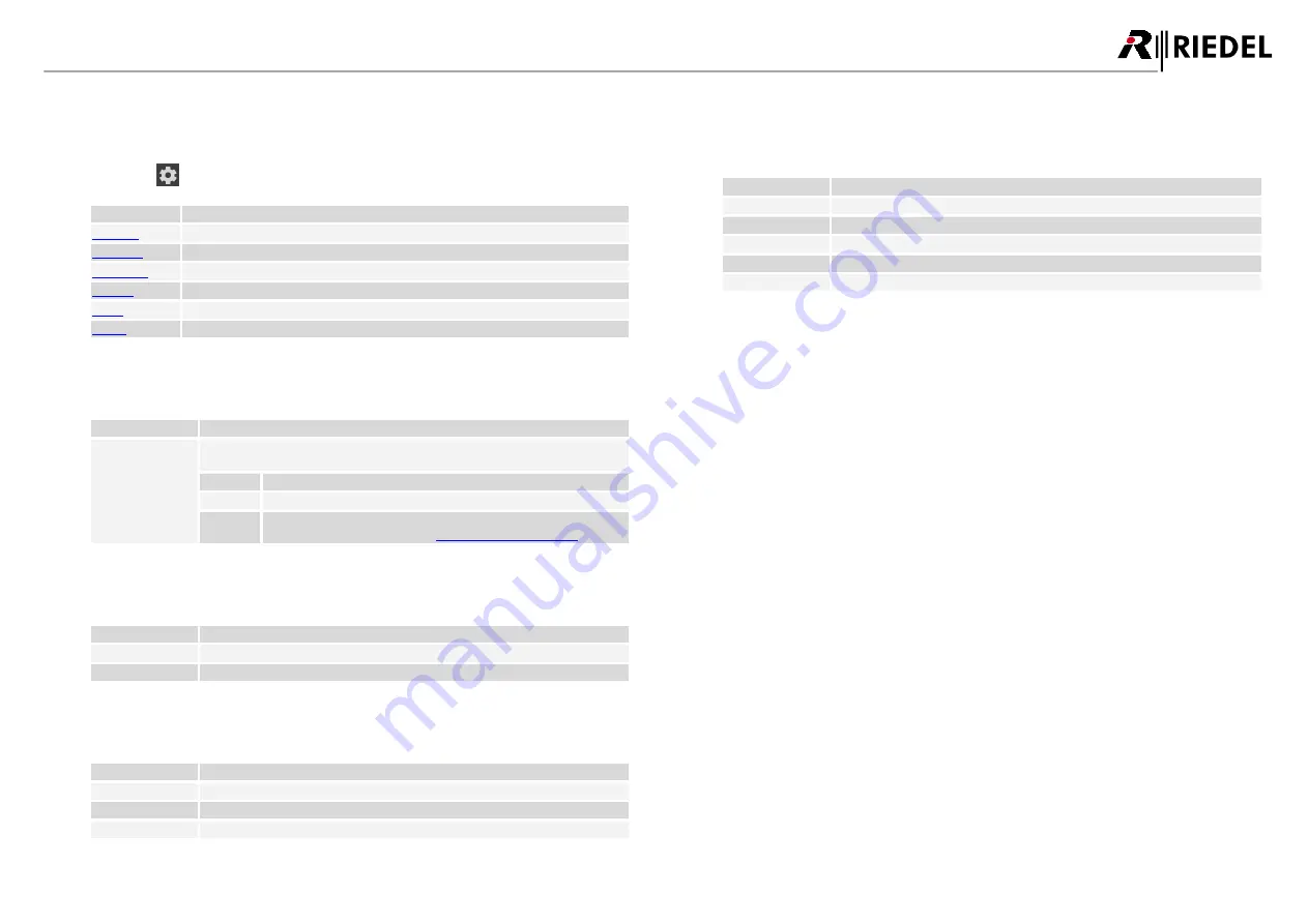
Panel-Menu

Basic information and settings of the SmartPanel can be displayed and modified in the Panel menu.

Ø

Touch the 

 gear icon on the Info-Display to open the Panel menu.

Info-display

Function

Transport

Set Transport Mode (

AES3

 or 

AES67

)

Brightness

Adjust brightness off displays and LEDs

Device-Info

Show SmartPanel information

Network

Show/edit network settings

Matrix

Show Matrix information

Service

Stores a log file and reboots the SmartPanel

4.1

Transport

The menu 

Transport

 allows selecting the protocol that is used to connect the SmartPanel with a matrix.

Info-display

Function

Selected Mode:

Display of the current selected mode.
The mode can be changed by pressing and turning the small rotary encoder.

AES3 Cat

The SmartPanel establishes a connection via RJ45 matrix connector.

AES3 Coax

The SmartPanel establishes a connection via BNC matrix connector.

AES67

The SmartPanel established a connection via the Ethernet-port defined
for using AES67 (see panel-menu: 

Network>AES67: Media-Port

).

4.2

Brightness

The menu 

Brightness

 allows adjusting the display and LED brightness between 10% and 100%.

Info-display

Function

Display Brightness:

Adjusting the brightness of the displays.

LED Brightness:

Adjusting the brightness of the key rings.

4.3

Device-Info

The menu 

Device-Info

 shows information about the SmartPanel.

Info-display

Function

Date:

Shows the current date.

FW Version:

Shows the current firmware version.

SN#:

Shows the serial number of the SmartPanel.

4.4

Network

The menu 

Network

 allows showing/editing network settings.

The menu 

AES67

 allows configuring the AES67 interface.

Info-display

Function

IP Address

Static IP-address of the AES67-port.

Subnet Mask

Network mask of the AES67-port.

Gateway

Gateway of the AES67-port.

SIP Port

Selection of the SIP-port. (Standard 5060)

Media Port

Selection of the Ethernet-port (ETH1...4) that is connected to the AES67 network.

DRAFT

05.10.2020

Содержание SmartPanel 1200 Series

Страница 1: ...1200 series User Manual 01 000HB03EG B00 SmartPanels 1 1 D R A F T 0 5 1 0 2 0 2 0 ...

Страница 2: ... been tested and found to comply with the limits for a Class A digital device pursuant to Part 15 of the FCC Rules These limits are designed to provide reasonable protection against harmful interference when the equipment is operated in a commercial environment This equipment generates uses and can radiate radio frequency energy and if not installed and used in accordance with the instruction manu...

Страница 3: ... 6 Info Display 20 3 7 Replacing the Air Filter 21 3 8 Technical Specifications 22 3 9 Reset 23 4 Panel Menu 24 4 1 Transport 24 4 2 Brightness 24 4 3 Device Info 24 4 4 Network 24 4 5 Matrix 25 4 6 Service 25 5 SmartPanel Firmware 26 5 1 Licensing 26 5 2 Intercom App 26 5 2 1 Operation 26 5 2 2 Signalization 28 5 2 3 Lever Groups 29 5 2 4 Operation Mode 30 5 2 5 Key Banks 30 5 3 Web Interface 31 ...

Страница 4: ...ommitment by Riedel Communications GmbH Co KG or its suppliers Riedel Communications GmbH Co KG gives no warranty of any kind with regard to this manual or the software including but not limited to the implied warranties of merchantability and fitness for a particular purpose Riedel Communications GmbH Co KG shall not be liable for any errors inaccuracies or for incidental or consequential damages...

Страница 5: ...ment components for any reason Caution All adjustments have been done at the factory before the shipment of the devices No maintenance is required and no user serviceable parts are inside the module Ventilation Do not place the devices next to a hot source like a radiator The ventilation openings of the devices must never be blocked Environment Never place the devices in an area of high dust parti...

Страница 6: ...001 11 in the wavelength range from 400 nm to 1 400 nm for the classification of a laser is the same between 100 s and 30 000 s Therefore nuisances cannot be ruled out in the case of long term effects Disposal Disposal of old Electrical Electric Equipment Applicable throughout the European Union and other European countries with separate collection programs This symbol found on your product or on ...

Страница 7: ...nel s firmware and bugfix version figure 1 firmware version SmartPanel Web Interface Enter the IP address of the AES67 interface Ethernet connectors of the SmartPanel in the web browser of a PC on the same network The IP addresses of the SmartPanel are displayed in the Panel Menu Network AES67 figure 2 IP address of the SmartPanel Open the web interface of the SmartPanel Enter the IP address in th...

Страница 8: ...ws where the user chooses what to listen to from an initially silent panel Other workflows prefer a Talk Mute workflow where users start with a panel that broadcasts everything with the users selectively choosing which signals to turn off Users decide which mode they prefer on a per panel basis Inventing a panel from scratch also enables new features that greatly aid in making the panel easier to ...

Страница 9: ...6 front view RSP 1216HL figure 7 rear view RSP 1216HL Panel Microphone Connector 6 3 mm jack 1 Key Displays Touchscreen 2 Light Sensor future use 1 NFC Antenna Bluetooth Antenna future use 1 1 Info Display Touchscreen 1 Speaker 1 Headset Connectors front XLR rear RJ45 1 2 Lever Keys with integrated Rotary Encoders with push functionality 16 Internal Panel Microphone future use 1 Rotary Encoder lef...

Страница 10: ...eactivated LED Ring top bottom RGB Depending on operation mode Group Color Signalization Rotary Encoder left volume red blinking Speaker muted off Speaker active Rotary Encoder right sidetone red blinking Microphone muted off Microphone open Ethernet left green Activity off No activity Ethernet right yellow 100 Mbit s link to the Intercom Network present green 1 Gbit s link to the Intercom Network...

Страница 11: ...work Address IP address of the AES67 port Media Port Selection of the Ethernet port that is connected to the AES67 network Transport Selected Shows the current selected transport mode Matrix State of the connection to the matrix figure 11 info display RSP 1216HL no connection If the SmartPanel is connected to the matrix the matrix status changes to RX TX OK before the default view is displayed fig...

Страница 12: ... encoder in the respective lever key The volume level is temporarily visualized by a horizontal bar on the corresponding Key display Pushing the rotary encoder will mute the corresponding port Muting is also possible by turning down the volume completely This is indicated by a mute icon in the corresponding Key display figure 14 Port Volume RSP 1216HL Sidetone Volume The left grey rotary encoder i...

Страница 13: ...ns to a remote station the Listen symbol is displayed Talk Mute If at least one channel on the Key Bank is muted the Mute symbol is displayed Wipe from right to left on the info display to show the menu Speaker Headset Switching between speaker and headset Speaker SmartPanel speaker and microphone are active Headset The connected headset is active Info Gear Opening the Panel Menu Open the Panel Me...

Страница 14: ...alog audio 4 wire inputs and outputs 2 Headset Headset A is identical to front connector signal BNC 1 Matrix connector for matrix connection AES3 DisplayPort 1 DisplayPort connector Sub D9 male 3 GPI output max 48 V 300 mA protected by self healing fuse Sub D9 female 3 GPI input 5 V 48 V Audio Maximum Level Audio A B Output 24 dBu 0 dBFS 2 kΩ load 23 dBu 0 dBFS 600 Ω load Audio A B Input 24 dBu 0 ...

Страница 15: ...orm factor 19 1RU Weight 2 3 kg 5 1 lbs Cooling fan noise speed temperature controlled 23 dB A idle 34 dB A max fan speed 0 7m low noise emission according GK15 DIN 15996 Environment operating temperature 0 45 C storage temperature 30 80 C humidity 20 90 relative non condensing max altitude 3000 m absolute 2 8 Reset A restart of the SmartPanel can be forced in the panel menu Service Reboot Panel D...

Страница 16: ...figure 18 RSP 1232HL front view figure 19 RSP 1232HL rear view Panel Microphone Connector 6 3 mm jack 1 Key Displays Touchscreen 2 Lever Keys with integrated Rotary Encoders with push functionality 32 Internal Panel Microphone future use 1 Light Sensor future use 1 Rotary Encoder big with push functionality 1 Speaker left right 2 Headset Connectors front XLR rear RJ45 1 2 NFC Antenna Bluetooth Ant...

Страница 17: ...crophone deactivated LED Ring top bottom RGB Depending on operation mode Group Color Signalization Rotary Encoder big red blinking Speaker muted off Speaker active Rotary Encoder small red blinking Microphone muted off Microphone open Ethernet left green Activity off No activity Ethernet right yellow 100 Mbit s link to the Intercom Network present green 1 Gbit s link to the Intercom Network presen...

Страница 18: ...k Address IP address of the AES67 port Media Port Selection of the Ethernet port that is connected to the AES67 network Transport Selected Shows the current selected transport mode Matrix State of the connection to the matrix figure 23 Info display no connection If the SmartPanel is connected to the matrix the matrix status changes to RX TX OK before the default view is displayed figure 24 RSP 123...

Страница 19: ...ncoder in the respective lever key The volume level is temporarily visualized by a horizontal bar on the corresponding Key display Pushing the rotary encoder will mute the corresponding port Muting is also possible by turning down the volume completely This is indicated by a mute icon in the corresponding Key display figure 26 Port Volume RSP 1232HL Sidetone Volume The lower small rotary encoder i...

Страница 20: ... Listen This symbol depends of the operation mode Talk Listen If at least one channel on the Key Bank listens to a remote station the Listen symbol is displayed Talk Mute If at least one channel on the Key Bank is muted the Mute symbol is displayed Speaker Headset Switching between speaker and headset Speaker SmartPanel speaker and microphone are active Headset The connected headset is active Gear...

Страница 21: ...Ø Use your fingers to pull out the grille including the air filter on the upper side Ø Remove the air filter out of the grille Ø Push the new cleaned air filter in the grille Ø Insert the grille into the bottom of the SmartPanel first and then press it evenly Ø Repeat this step on the opposite side of the chassis D R A F T 0 5 1 0 2 0 2 0 ...

Страница 22: ...nalog audio 4 wire inputs and outputs 2 Headset Headset A is identical to front connector signal BNC 1 Matrix connector for matrix connection AES3 DisplayPort 1 DisplayPort connector Sub D9 male 3 GPI output max 48 V 300 mA protected by self healing fuse Sub D9 female 3 GPI input 5 V 48 V Audio Maximum Level Audio A B Output 24 dBu 0 dBFS 2 kΩ load 23 dBu 0 dBFS 600 Ω load Audio A B Input 24 dBu 0...

Страница 23: ...orm factor 19 2 RU Weight 3 4 kg 7 4 lbs Cooling fan noise speed temperature controlled 23 dB A idle 26 dB A max fan speed 0 7m low noise emission according GK15 DIN 15996 Environment operating temperature 0 45 C storage temperature 30 80 C humidity 20 90 relative non condensing max altitude 3000 m absolute 3 9 Reset A restart of the SmartPanel can be forced in the panel menu Service Reboot Panel ...

Страница 24: ... establishes a connection via BNC matrix connector AES67 The SmartPanel established a connection via the Ethernet port defined for using AES67 see panel menu Network AES67 Media Port 4 2 Brightness The menu Brightness allows adjusting the display and LED brightness between 10 and 100 Info display Function Display Brightness Adjusting the brightness of the displays LED Brightness Adjusting the brig...

Страница 25: ...eit Shows the current time of the connected matrix MIC conf The microphone setting of the panel can be changed between dynamic and electret by using the lever key 29 HS conf The microphone setting of the headset can be changed between dynamic and electret by using the lever key 31 4 6 Service The menu Service allows storing logfiles and rebooting the SmartPanel Info display Function Log Files Stor...

Страница 26: ...App The first SmartPanel app turns the SmartPanels in innovated and intelligent intercom panels Riedel s intercom app can be quickly and easily upgraded to the desired edition without changing any hardware components This app requires a license file This license is already pre installed on the SmartPanel Intercom App RSP 1216HL APP PRO RSP 1232HL APP PRO Intercom Keys 16 32 Multi Touch Displays 3 ...

Страница 27: ...to the lever up key function In Talk Mute mode the activated monitoring function is indicated by an ear icon in the upper right area Sets the volume of the corresponding channel to normal level or switches off the muting Configures the copy reply button to this port Scroll Lists To call up scroll lists configured in the Director on a 1200 smart panel the respective configured rotary encoder must b...

Страница 28: ... mic icon in the upper left area indicates an active outgoing call Mute active The red mute icon in the upper right area indicates a muted port Talk Listen Modus In Talk Listen mode the signalization depends on the configuration of the group color If the group color is indicated via the key ring the signalization is indicated via the display If the group color is indicated via the display the sign...

Страница 29: ...in the Director software right click on the respective key Properties General tab Group color The group color is indicated either in the key ring or in the display of the SmartPanel This setting is done in Panel Properties in the Director software right click on the respective SmartPanel Properties UI Config tab Group color figure 33 group color per key in Director Key Properties figure 34 indicat...

Страница 30: ...panel Execute additional configured commands 1 latching only 2 auto momentary and latching 5 2 5 Key Banks Key Banks a new take on shift pages are layers of keys that are accessed by simply touching a button on the screen The Info Display shows two key banks in the main The user can switch between the key banks by touching the respective name for 0 5 seconds The active key bank is highlighted in t...

Страница 31: ...Update Opens the firmware manager Parameter Drawer The inputs outputs of the audio paths A B can be defined 5 3 1 Asset Drawer The asset drawer shows all SmartPanels found in the network Double Clicking an entry opens the SmartPanel in the Work Surface figure 39 Asset Drawer Enter a text in this search field to filter the displayed elements The filtering starts while filling this field it is not n...

Страница 32: ...y clicking the horizontal arrows Ø Finally confirm your change by clicking the OK button 5 3 2 Work Surface The work surface the user defined key assignments of the SmartPanel are displayed and configured A SmartPanel can be opened in the Work Surface by double clicking it in the Asset Drawer figure 40 Work Surface ONLINE indicates an active Ethernet connection to the SmartPanel OFFLINE indicates ...

Страница 33: ...tch is enabled the firmware of all found SmartPanels is updated If the switch is disabled the firmware can be updated individually on SmartPanels 5 3 4 Parameter Drawer In the parameter drawer the inputs outputs of the audio paths A B can be defined Audio A B The Audio A and Audio B tabs are used to configure the input and output of the audio patch figure 42 Audio A B Parameter Drawer Audio A B In...

Страница 34: ...Inputs only 2 Audio A only Packet Settings Packet Time Packet time is the real time duration of media data in a packet Samples per packet are calculated from packet time and sampling rate Short packet time allows for lower latency but requires more bandwidth due to overhead Implemented for interoperability reasons Depending of selected amount of audio channels and the bit depth shorter packet time...

Страница 35: ...o be renamed All names are accepted Ø When the RSP 1232HL SmartPanel is booted insert the USB pen drive into the USB connector below the Info display The update process is started automatically Do not power cycle the panel and do not remove the USB pen drive until the update procedure is finished Ø The firmware is uploaded in the SmartPanel now figure 45 update in progress Ø After storing the firm...

Страница 36: ... Open on the right side the main menu of the SmartPanel and select Firmware Update figure 50 Firmware Update The firmware manager opens Click on the SELECT FW button Navigate to the location of the firmware file and select the desired one by clicking the Open button figure 51 select firmware Click on the INSTALL button figure 52 install The selected firmware is transferred into the SmartPanel A ba...

Страница 37: ...ameter Drawer figure 59 Audio A B tab Change the setting from Analogue default to AES67 for each 4 wire s individual input or output channel figure 60 Analogue AES67 Click on Stream Setup figure 61 stream setup 1 Enter the stream parameters 2 Alternatively the parameters can be loaded via a SDP file by clicking the button Import SDP figure 62 stream parameter In Audio A Parameter Drawer Activate t...

Страница 38: ... by clicking the button at the top of the web interface figure 65 change channel When you switch back to the 4 wire analog system your AES67 configuration is saved for later use figure 66 stored stream parameters Route your AES67 or analogue inputs outputs in the Director audiopatch as you prefer it for your setup figure 67 routing in the Director audiopatch D R A F T 0 5 1 0 2 0 2 0 ...

Страница 39: ...k that is separated from the intercom network This port is 100Base T compatible 1 8 Pin Signal Standard color 1 TX orange white 2 TX orange 3 RX green white 4 blue 5 blue white 6 RX green 7 brown white 8 brown figure 69 MGNT connector RJ 45 pinout 8P8C Expansion port The Expansion connector is used to connect Expansion Panels 1 8 Pin Signal Standard color 1 TX orange white 2 TX orange 3 RX green w...

Страница 40: ...al must be connected to P of each channel The inputs are galvanically isolated The GPIO 5V output voltage drops by increasing the load 5V 0mA 3 3V 50mA GPI OUT port The GPI output connector contains 3 single ports 6 9 1 5 Pin Signal Pin Signal 1 GP OUT1 P 6 GP OUT1 N 2 GP OUT2 P 7 GP OUT2 N 3 GP OUT3 P 8 GP OUT3 N 4 9 5 Chassis Chassis Chassis figure 75 GPI OUT connector Sub D 9 male pinout GND GP...

Страница 41: ...r block diagram Headset connectors 1 8 Pin Headset A Headset B 1 HS Phones A right HS Phones B right 2 GND GND 3 Data A Data B 4 HS MIC A 5 VDC HS MIC B 5 VDC 5 HS MIC A GND HS MIC B GND 6 PTT A PTT B 7 HS Phones A left HS Phones B left 8 GND GND Case Chassis Chassis figure 79 Headset connector RJ 45 pinout 1 2 3 4 Pin Headset A Headset B 1 HS MIC A GND HS MIC B GND 2 HS MIC A 5 VDC HS MIC B 5 VDC...

Страница 42: ...ion Support Trainings Repair Your primary point of contact for any service issues is your local dealer In addition Riedel Customer Service in Wuppertal Germany is also available to assist you Telephone 49 0 202 292 9400 Monday Friday 8am 5pm Central European Time Fax 49 0 202 292 9419 Or use the contact form on our website www riedel net Services Support For repairs please contact your local deale...

Страница 43: ... Key Display Functions Intercom App 27 Keystrokes 15 23 L Laser Safety 6 LED Brightness 24 Lever Key Numbering Intercom App 18 Lever Key Numbering RSP 1216HL 11 Lever Groups 29 Lever Key Functions Intercom App 26 Licensing 26 Log Files 25 M Maintenance Recommendations 42 Master Volume 12 19 Matrix Panel Menu 25 Matrix connector pinout 39 MGNT 24 25 MGNT port pinout 39 Monthly Maintenance Recommend...

Страница 44: ...cations Overall 15 23 Technical Specifications Rear Elements 14 22 Technical Specifications RSP 1216HL 14 Technical Specifications RSP 1232HL 22 Telephone 42 Trainings 42 Transport Panel Menu 24 U USB pen drive Firmware Update 35 V Ventilation 5 Voltage 5 Voltage GPI OUT port 40 Voltages GPI IN port 40 Volume Master 12 19 Volume Port 12 19 Volume RSP 1216HL 12 Volume RSP 1232HL 19 Volume Sidetone ...

Страница 45: ...www riedel net Riedel Communications GmbH Co KG Uellendahler Str 353 42109 Wuppertal Germany 01 000HB03EG B00 D R A F T 0 5 1 0 2 0 2 0 ...

Отзывы: