background image

8   –   English

nano

TM

1

2

Figure 8  –  Locking the Slip-Ring Module Cover

Reversing/Installing the Display Cradle 
(micro CA-300 Inspection Camera)

If using the nanoReel with the micro CA-300, it may 

be more convenient to face the micro CA-300 display 
the other way when seated in its cradle. To reverse the 

orientation of the cradle, perform the following:

1. Remove the micro CA-300 from the cradle 

(See

Item 1, Figure 9)

. Use a Philips screwdriver to

remove the four screws holding the cord wrap arms
and the cradle’s support arms to the case openings

(See Item 2 and Item 3, Figure 9)

. Remove the

cord-wrap arms after removing the screws.

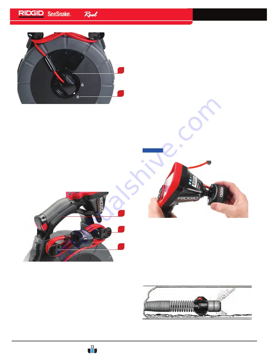
1

2

3

Figure 9  –  Cradle Support and Cord-Wrap Arms

2. Use one of the screws to remove the nuts from

the backside of the cradle. The nuts are friction-
fitted into the holes on the opposite side of the
cradle from the cord-wrap arms. Extract the nut by
inserting a screw from the back and threading it
two or three turns into the nut.

3. Without taking the nut off, insert the screw and nut

into the hole on the opposite side of the case. Tap
the screw firmly with the handle of the screwdriver
to seat the nut into the friction-fit at the bottom of
the hole.

4. Unthread the screw. Repeat for each of the

remaining three nuts.

5.  Position the cord-wrap arm and cradle on the same

side of the case, facing in the opposite direction.
Make sure the cord-wrap horns point outward.

6. Start each screw into its nut by hand. Tighten the

screws hand-tight with a screwdriver.

7. Replace the display unit in the cradle.

Install the display cradle using a similar process.

Connecting the micro CA-300 Inspection 
Camera to the nano

Reel

 System

Align the micro CA-300 Camera Connector Plug with the 

plug on the micro CA-300 Camera, slide it straight in, 
and seat it squarely. The curved face of the connector 
plug on the system cable faces upward, sliding under 
the forward edge of the micro CA-300 camera monitor 
when fully seated (

See Figure 10)

.

NOTICE 

To prevent damaging the plug, do not twist 

the connector plug.

Figure 10  –  Connecting the micro CA-300 Camera 

Monitor

nanoReel


Ball Guides

Ball guides help center the camera in pipes and keeps 
the camera clear of bottom sludge in the pipe. Ball 
guides also improve picture quality, allows the camera 
to see equally in all directions, and keeps the lens free 
of sludge by bringing the camera closer to the center of 
the pipe. 

Figure 11  –  Ball Guide in Use

www.calcert.com

[email protected]

1.800.544.2843

0

5

10

15

20

25

30

Содержание SeeSnake NanoReel

Страница 1: ...lure to under stand and follow the con tents of this manual may result in electrical shock fire and or serious person al injury Operator s Manual Record product serial number below as it appears on th...

Страница 2: ...Legend 6 Assembly 7 Camera Head Routing 7 Installing System Cable 7 Reversing Installing the Display Cradle micro CA 300 inspection Camera 8 Connecting the micro CA 300 Inspection Camera to the nanoR...

Страница 3: ...ective equipment Always wear eye protection The appropriate use of protective equipment such as a dust mask non skid safety shoes a hard hat and hearing protection will reduce personal injuries t Do n...

Страница 4: ...ead these precautions carefully before using the nanoReel to reduce the risk of electrical shock fire or other serious personal injury SAVE ALL WARNINGS AND INSTRUCTIONS FOR FUTURE REFERENCE Keep this...

Страница 5: ...mera inspection through pipes with very small diameters P traps and very small radius bends which conventional inspection systems often cannot inspect When using the nanoReel with an appropriate SeeSn...

Страница 6: ...ch Camera Head Figure 2 Inside Case Figure 3 Rear View with the micro CA 300 inspection camera Icon Legend Table 2 micro CA 300 Icons Icon Meaning Return Key Shutter Key Select Key Arrow Keys Power Ke...

Страница 7: ...head in the provided clip See Figure 6 6 Close and relatch the case Figure 5 Routing the Camera Head Figure 6 Camera Head Properly Routed Installing System Cable NOTICE Do not touch the contact pins...

Страница 8: ...the friction fit at the bottom of the hole 4 Unthread the screw Repeat for each of the remaining three nuts 5 Position the cord wrap arm and cradle on the same side of the case facing in the opposite...

Страница 9: ...two halves around the camera head with their screw holes aligned 3 Fasten the two halves together with the two screws provided Do not over tighten Pre Operation Inspection WARNING Before each use ins...

Страница 10: ...sleeve and match the System Cable plug to the matching SeeSnake System Connector on the CCU See Item 1 Figure 13 2 To join the connectors align the guide pin to the guide socket push the connector str...

Страница 11: ...ent the image at the bottom of the pipe This can be done by placing a hose down the line or turning on a fixture for example flushing a toilet Shut off water flow as needed for viewing 6 Grip the push...

Страница 12: ...d stress the push cable Figure 16 Avoid Pulling at Sharp Angles When inspecting the line try moving the camera head past the area to be inspected and slowly pull it back for better results Pulling the...

Страница 13: ...location precisely For detailed instructions on Sonde locating consult the operator s manual for the locator model you are using Figure 20 Locating the nanoReel Sonde Retrieving the Camera After comp...

Страница 14: ...to function with the nanoReel Other accessories suitable for use with other tools may become haz ardous when used with the nanoReel To reduce the risk of serious injury only use accessories spe cific...

Страница 15: ...t and its implementation into national legislation electrical equipment that is no longer usable must be collected separately and disposed of in an environmentally correct manner Table 3 Troubleshooti...

Страница 16: ...Printed in U S A 1 5HY www calcert com sales calcert com 1 800 544 2843 0 5 10 15 20 25 30...

Отзывы: