background image

  1.  Remove battery from tool.
 2. Clean any oil, grease or dirt from the 

equipment, especially the handles and 

controls. This aids inspection and helps 

to prevent the tool or controls from slip-

ping from your grip.

  3.  Inspect the press tool for:


•  Proper assembly, maintenance and 

completeness.


•   Any broken, worn, missing, misaligned 

or binding parts. Confirm fabric loops 

are in good condition.


•  Smooth movement of attachment 

mounting pin between the fully open 

and fully closed position. Pin should 

lock into each position. Confirm that 

the run switch moves freely and does 

not bind or stick.  


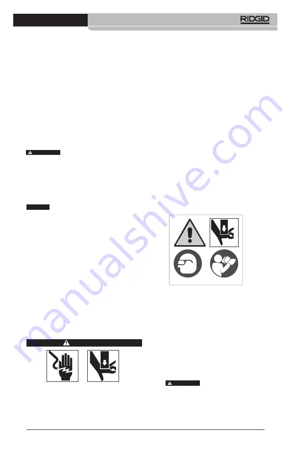
•  Presence and readability of warning 

label 

(Figure 1 or 6)

.


•   Any other condition which may prevent 

safe and normal operation.


   Do not use the press tool until problems 

have been repaired.

Figure 6 –  Warning Label  

  4.  Inspect the attachments:


•    Closely inspect all attachments for any 

cracked, broken, worn, missing, mis-

aligned or binding parts or any other 

sign of damage that may prevent prop-  

er and safe operation. Damaged parts 

can cause the attachment to make 

incorrect pressed connections or fail 

during use and cause serious injury 

or property damage. If any damage is 

found, the attachment should be dis-

carded and replaced.


Always discard the com- 

plete pressing attachment. Never re- 

place individual components or ex- 

change parts between assemblies. 

Failure to replace the entire assembly 

may result in component failure and 

serious injury.

- Vibration levels may be used for comparison with 

other tools and for preliminary assessment of expo-

sure.

- Sound and vibration emissions may vary due to your 

location and specific use of these tools.

- Daily exposure levels for sound and vibration need 

to be evaluated for each application and appropriate 

safety measures taken when needed. Evaluation of 

exposure levels should consider the time a tool is 

switched OFF and not in use. This may significant-

ly reduce the exposure level over the total working 

period.

#  All specifications are nominal and may change as 

design improvements occur.

Standard Equipment

Refer to the RIDGID catalog for details on 

equipment supplied with specific tool cata-

log numbers.

 Only use RIDGID Press Tools 

and RIDGID press tool attachments when 

specified by the fitting manufacturer for use 

with their system. Use of incorrect press tools 

and/or attachments for a system can cause 

system leaks, damage the press tool or 

attachment, void warranties or cause severe 

personal injury.

 Selection of a appropriate materi-

als and joining methods is the responsibil-

ity of the system designer and/or installer. 

Before any installation is attempted, careful 

evaluation of the specific service environ-

ment, including chemical environment and 

service temperature, should be completed. 

Consult Press Fitting System manufacturer 

for selection information.
Contact the fitting manufacturer for specific 

information on their system, including com-

patible tubing, materials, installation instruc-

tions, minimum distance between fittings, 

seal material, inspection, testing, etc. Incor-

rect installation can cause system leaks and 

extensive property damage.

Pre-Operation 

Inspection 

 WARNING

Daily before use, inspect your press tool 

and attachments. Correct any problems 

to reduce the risk of serious injury from 

electric shock, crushing injures, attach-

ment failure and other causes, and pre-

vent tool damage. 

999-995-408.10_REV. A

7

RP 115 Press Tool

NOTICE

WARNING

HE.20079

WARNING

Содержание RP 115

Страница 1: ...Installing Attachment 8 Preparing Connection 9 Pressing A Fitting 9 Inspecting The Pressed Connection 10 Work Light Disable Enable 10 Storage 10 Maintenance Instructions Cleaning And Lubrication 10 Pr...

Страница 2: ...P 115 PressTool WARNING Read this Operator s Man ual carefully before using this tool Failure to understand and follow the contents of this manual may result in electrical shock fire and or serious pe...

Страница 3: ...tions illustrations and specifications provided with this power tool Failure to follow all instructions listed below may result in electric shock fire and or serious injury SAVE ALL WARNINGS AND INSTR...

Страница 4: ...g tools sharp and clean Pro perly maintained cutting tools with sharp cutting edges are less likely to bind and are easier to control the power tool Keep cord away from heat oil sharp edges or moving...

Страница 5: ...bits etc in accordance with these instructions taking into account the working conditions and the work to be performed Use of the power tool for oper ations different from those intended could result...

Страница 6: ...any other equip ment or material used with this tool Failure to follow all instructions and warn ings may result in property damage and or serious injury RIDGID Contact Information If you have any qu...

Страница 7: ...cked Tool has completed service interval 20 000 cycles and requires service Tool has malfunctioned Remove and reinsert battery If still ON have tool serviced 20 sec 2Hz Figure 5 Tool Status Lights Con...

Страница 8: ...these tools Daily exposure levels for sound and vibration need to be evaluated for each application and appropriate safety measures taken when needed Evaluation of exposure levels should consider the...

Страница 9: ...severe injury or death Discard and replace damaged pressing attach ments Inspect the attachment markings to make sure that it is clearly marked as to the system and size that it is appro priate for Do...

Страница 10: ...mpletion If the tool malfunc tions during operation use this proce dure fully closed to prevent tool damage during use NOTE Do not operate tool without the attach ment in place this can damage the too...

Страница 11: ...sed to make the pressed connection This witness mark is a trade mark of the Ridge Tool Company Ab sence of the witness mark may invalidate the system manufacturer s warranty Figure 12 ProPress Witness...

Страница 12: ...es These methods may alter critical pressing profile dimensions and cause improper pressed connections that can lead to extensive property damage Figure 13 Fitting Material Build Up Requiring Jaw Clea...

Страница 13: ...ops during operation Troubleshooting Cont Fitting material build up in the con toured profile area near jaw tips Excessively worn or damaged jaws Fitting material build up in the con toured profile ar...

Страница 14: ...s no longer usable must be collected separately and disposed of in an environmentally correct manner Clearance Requirements The following figures illustrate the clearance requirements for the jaws and...

Страница 15: ...nment where electromagnetic radiation and electrostatic discharges are present and without causing electromagnetic interference to other equip ment These tools conform to all applica ble EMC standards...

Отзывы: