background image

5 - English

ASSEMBLY

WARNING:

Do not use this product if it is not completely 
assembled or if any parts appear to be missing or 
damaged. Use of a product that is not properly and 
completely assembled or with damaged or missing 
parts could result in serious personal injury.

WARNING:

Do not attempt to modify this product or create 
accessories not recommended for use with this 
product. Any such alteration or modification is 
misuse and could result in a hazardous condition 
leading to possible serious personal injury.

If any parts are damaged or missing, please call 1-866-539-1710 for assistance.

OPERATION

WARNING:

Do not allow familiarity with tools to make you 
careless. Remember that a careless fraction of a 
second is sufficient to inflict severe injury.

WARNING:

Always remove battery pack from the tool when 
you are assembling parts, making adjustments, 
cleaning, or when not in use. Removing battery 
pack will prevent accidental starting that could 
cause serious personal injury.

WARNING:

Always wear eye protection with side shields 
marked to comply with ANSI Z87.1. Failure to do 
so could result in objects being thrown into your 
eyes, resulting in possible serious injury.
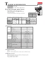
APPLICATIONS

You may use this tool for the purposes listed below:

 

Driving nuts and bolts using an impact socket

INSTALLING / REMOVING BELT HOOK

See Figure 1, page 8

.

  Align hole in belt hook with hole in the housing.

  Install screw to secure belt hook in place.

  To uninstall, remove screw then remove belt hook.

VARIABLE SPEED SWITCH TRIGGER

See Figure 2, page 8.

The variable speed switch trigger delivers higher speed with 
increased trigger pressure and lower speed with decreased 
trigger pressure.
To turn the tool 

ON

, depress the switch trigger. To turn it 

OFF

, release the switch trigger and allow the anvil to come 

to a complete stop.

NOTE:

  A whistling or ringing noise coming from the switch 

during use is a normal part of the switch function.

DIRECTION OF ROTATION SELECTOR

(FORWARD/REVERSE/CENTER LOCK)

See Figure 2, page 8.

Set the direction of rotation selector in the OFF (center lock) 
position to lock the switch trigger and help prevent accidental 
starting when not in use.
Position the direction of rotation selector to the left of the 
switch trigger for forward operation. Position the selector to 
the right of the switch trigger to reverse the direction.

NOTE: 

The tool will not run unless the direction of rotation 

selector is pushed fully to the left or right.

NOTICE:

To prevent gear damage, always allow the anvil 

to come to a complete stop before changing the 

direction of rotation.

WARNING:

Battery tools are always in operating condition. 
Lock the switch when not in use or carrying at your 
side, when installing or removing the battery pack, 
and when installing or removing sockets.

INSTALLING/REMOVING BATTERY PACK

See Figure 3, page 8.


To install,

 lock the switch trigger and insert the battery 

pack.

  Make sure the latches on the side of the battery pack 

snaps in place and that battery pack is secured in the 
product before beginning operation.


To remove,

 depress the latches.

LED LIGHTS

See Figure 4, page 8.

The LED lights around the anvil illuminate when either the 
switch trigger or grip light switch is depressed.
If the tool is not in use, the time-out feature will cause the 
light to start fading and then shut off.
The LED light illuminates only when there is a charged battery 
pack in the tool.

Содержание R86010

Страница 1: ...Symboles 4 Assemblage 5 Utilisation 5 6 Entretien 7 Figures illustrations 8 Commande de pi ces et d pannage Page arri re NDICE DE CONTENIDO Advertencias de seguridad para herramientas el ctrica 2 3 A...

Страница 2: ...tive equipment Always wear eye protection Protective equipment such as dust mask non skid safety shoes hard hat or hearing protection used for appropriate conditions will reduce personal injuries Prev...

Страница 3: ...ation where the temperature is more than 50 F but less than 100 F To reduce the risk of serious personal injury do not store outside or in vehicles Under extreme usage or temperature conditions batter...

Страница 4: ...jury user must read and understand operator s manual before using this product Eye Protection Always wear eye protection with side shields marked to comply with ANSI Z87 1 Wet Conditions Alert Do not...

Страница 5: ...ith increased trigger pressure and lower speed with decreased trigger pressure To turn the tool ON depress the switch trigger To turn it OFF release the switch trigger and allow the anvil to come to a...

Страница 6: ...for the proper fastening time Remove the impact wrench from the nut or bolt Check the torque with a torque wrench NOTICE Do not use this tool to install lug nuts on wheels without a torque limiting d...

Страница 7: ...ctrique Ne pas utiliser cet outil en tat de fatigue ou sous l influence de l alcool de drogues ou de m dicaments Un moment d inattention pendant l utilisation d un outil lectrique peut entra ner des b...

Страница 8: ...p rature est de 10 38 C 50 100 F Ne pas ranger l outil l ext rieur ou dans un v hicule Si l outil est utilis de fa on intensive ou sous des temp ratures extr mes des fuites de pile peuvent se produire...

Страница 9: ...forme la norme ANSI Z87 1 Avertissement concernant l humidit Ne pas exposer la pluie ou l humidit Symboles de recyclage Ce produit utilise les piles de lithium ion Li ion Les r glementations locales o...

Страница 10: ...OURROIE Voir la figure 1 page 8 Aligner les trous du agrafe de courroie avec les trous du logement Installer le vis pour fixer solidement le agrafe de courroie Pour retirer d visser le vis et retire l...

Страница 11: ...fixation est d termin par le type de boulon la taille du boulon ou le type de mat riau ou la pi ce travailler Il est utile d effectuer un essai de fonctionnement afin de d terminer la dur e de fixatio...

Страница 12: ...rramienta el ctrica puede causar lesiones corporales serias Use equipo de seguridad Siempre p ngase protecci n ocular El uso de equipo de seguridad como mascarilla para el polvo calzado de seguridad c...

Страница 13: ...ta de bater as en un lugar donde la temperatura est entre 10 y 38 C entre 50 y 100 F No guarde la herramienta a la intemperie ni en el interior de veh culos En condiciones extremas de uso o temperatur...

Страница 14: ...I N Indica una situaci n peligrosa posible la cual si no se evita podr a causar lesiones menores o leves AVISO Sin el s mbolo de alerta de seguridad Indica informaci n importante no relacionada con ni...

Страница 15: ...Vea la figura 1 p gina 8 Alinee el orificio de clip del cintur n con el orificio de base Coloque el tornillo para asegurarla de clip del cintur n Para retirar afloje el tornillo y retirar el clip del...

Страница 16: ...guras 6 y 7 p gina 8 PRECAUCI N La superficie met lica puede calentarse durante el uso Evite tocarla para evitar toda posible lesi n por quemadura El tipo de perno el tama o del perno el material o la...

Страница 17: ...ver the battery pack s terminals with heavy duty adhesive tape Do not attempt to destroy or disassemble battery pack or remove any of its components Batteries must be recycled or disposed of properly...

Страница 18: ...cteur de sens de rotation verrouillage central selector de sentido de rotaci n adelante atr s seguro en el centro C Switch trigger g chette de commutateur gatillo del interruptor D Forward rotation av...

Страница 19: ...15 NOTES NOTAS...

Страница 20: ...t l phonique ou visite Pour obtenir l adresse du centre de r parations agr le plus proche t l phoner au 1 866 539 1710 ou visiter notre site www ridgid com Le num ro de mod le se trouve sur une plaque...

Отзывы: