background image

Page 6  — English

INSTALLING/REMOVING BITS

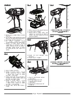
See Figures 3 - 4, page 7.

The tool has a built-in coupler that is designed to accept 
1/4 in. hex bits.

NOTE: 

Bits are not included.

To install bits:


Lock the switch trigger and remove the battery pack.

  Slide the coupler forward and hold in position.

  Insert bit straight into coupler.

  Slide the coupler back slowly and release.

  Reinstall the battery pack.

WARNING:

Make sure the bit is secured in the coupler before using 
the impact driver. Failure to do so could cause serious 
personal injury.

To remove bits:


Lock the switch trigger and remove the battery pack.

  Slide the coupler forward and pull the bit straight out of 

the coupler.

 

When not in use, bits can be placed in the storage area, 
located on the base of the tool.

 WARNING:

When servicing, use only identical replacement parts. 

Use of any other parts could create a hazard or cause 

product damage.

GENERAL MAINTENANCE

Avoid using solvents when cleaning plastic parts. Most 

plastics are susceptible to damage from various types of 

commercial solvents and may be damaged by their use. Use 
clean cloths to remove dirt, dust, oil, grease, etc.

BATTERY PACK REMOVAL AND 
PREPARATION FOR RECYCLING

 WARNING: 

Upon removal, cover the battery pack’s terminals with 

heavy-duty adhesive tape. Do not attempt to destroy or 

disassemble battery pack or remove any of its compo-

nents. Batteries must be recycled or disposed of properly. 

Also, never touch both terminals with metal objects and/

or body parts as short circuit may result. Keep away from 

children. Failure to comply with these warnings could 

result in fire and/or serious injury.

USING THE IMPACT DRIVER

See Figures 5 - 6, page 7.

WARNING:

Do not drive a screw where there is likely to be hidden 
wiring behind the surface. Contact with a “live” wire will 
make exposed metal parts of the tool “live” and shock 
the operator. If you must drive a screw where hidden wire 
may be present, always hold tool by insulated gripping 
surfaces (handle) when performing the operation to 
prevent a shock to the operator.

WARNING: 

The metal surface can become hot during use. Avoid 
contact with it to avoid possible burn injury.

NOTICE:

The impact driver is not designed to be used as a drill. 

  Check the direction of rotation selector for the correct 

setting (forward or reverse).

  Hold the impact driver with one hand.

  Place the bit on the screw head and slowly depress the 

switch trigger. Start the bit slowly for more control.

  As screw is driven, impacting will begin.

OPERATION

MAINTENANCE

Figures (Illustrations) start on page 8 after French and Spanish language sections.

This product has a Three-year Limited Warranty. 

For Warranty details go to www.powerstroketools.com

Содержание Power Stroke PSL0D181

Страница 1: ...ion 5 6 Entretien 7 Figures illustrations 8 Commande de pi ces et d pannage Page arri re INCLUYE Destornillador de impacto de 1 4 pulg manual del operador NDICE DE CONTENIDO Advertencias de seguridad...

Страница 2: ...ye protection Protective equipment such as dust mask non skid safety shoes hard hat or hearing protection used for appropriate conditions will reduce personal injuries Prevent unintentional starting E...

Страница 3: ...reduce the risk of serious personal injury do not store outside or in vehicles Under extreme usage or temperature conditions battery leakage may occur If liquid comes in contact with your skin wash im...

Страница 4: ...ohibit disposal of batteries in ordinary trash Consult your local waste authority for information regarding available recycling and or disposal options V Volts Voltage min Minutes Time Direct Current...

Страница 5: ...the switch trigger and help prevent accidental starting when not in use Position the direction of rotation selector to the left of the switch trigger for forward operation Position the selector to the...

Страница 6: ...th heavy duty adhesive tape Do not attempt to destroy or disassemble battery pack or remove any of its compo nents Batteries must be recycled or disposed of properly Also never touch both terminals wi...

Страница 7: ...uipement de s curit tel qu un masque filtrant de chaussures de s curit d un casque ou d une protection auditive utilis dans des conditions appropri es r duira le risque de blessures viter les d marrag...

Страница 8: ...ques relatifs son utilisation Le respect de cette consigne r duira les risques d incendie de choc lectrique et de blessures graves Toujours porter une protection oculaire certifi e conforme la norme A...

Страница 9: ...ymboles permettra d utiliser produit plus efficacement et de r duire les risques SYMBOLE NOM D SIGNATION EXPLICATION Symbole d alerte de s curit Indique un risque de blessure potentiel Lire manuel d u...

Страница 10: ...tion ou du retrait des forets INSTALLATION RETRAIT DU BLOC PILES Voir la figure 2 page 7 Pour ins rer verrouiller la g chette et ins rer la pile S assurer que les loquets de chaque c t de la pile s en...

Страница 11: ...ns le compartiment se trouvant sur le haut de l outil UTILISATION Utilisation de cl chocs Voir les figures 5 et 6 page 7 AVERTISSEMENT Ne pas enfoncer de vis dans des surfaces pouvant dissimuler des f...

Страница 12: ...ir le piles couvrir ses bornes avec un ruban adh sif de qualit industrielle Ne pas essayer de d monter ou d truire le piles ni de retirer des composants quels qu ils soient Les piles puis es doivent t...

Страница 13: ...causar lesiones corporales serias Use equipo de seguridad Siempre p ngase protecci n ocular El uso de equipo de seguridad como mascarilla para el polvo calzado de seguridad casco y protecci n para lo...

Страница 14: ...uede causar p rdida Familiar cese con su herramienta el ctrica Lea cuidadosamente el manual del operador Aprenda sus usos y limitaciones as como los posibles peligros espec ficos de esta herramienta e...

Страница 15: ...LO NOMBRE DENOMINACI N EXPLICACI N Alerta de seguridad Indica un peligro posible de lesiones personales Lea manual del operador Para reducir el riesgo de lesiones el usuario debe leer y comprender el...

Страница 16: ...LOCIDAD VARIABLE Ver la figura 1 p gina 7 El gatillo de velocidad variable produce mayor velocidad cuanta mayor presi n se aplica en el gatillo y menor velocidad cuanta menor presi n se aplica en el m...

Страница 17: ...mienta Utilizar Destornillador de Impacto Vea las figuras 5 y 6 p gina 7 ADVERTENCIA No introduzca tornillos donde pudiera haber cables ocultos detr s de la superficie Todo contacto de una herramienta...

Страница 18: ...aquete de bater as PARA EL RECICLADO ADVERTENCIA Al retirar el paquete de bater as cubra las terminales del mismo con cinta adhesiva reforzada No intente destruir o desarmar el paquete de bater as ni...

Страница 19: ...1 A Coupler coupleur acoplador B Direction of rotation selector forward operaton s lecteur de sens de rotation rotation avant selector de sentido de rotaci n marcha atr s C Variable speed switch trig...

Страница 20: ...chemicals are lead from lead based paints crystallinesilicafrombricksandcementandothermasonryproducts__ and arsenic and chromium from chemically treated lumber Your risk from exposure to these chemic...

Отзывы: