background image

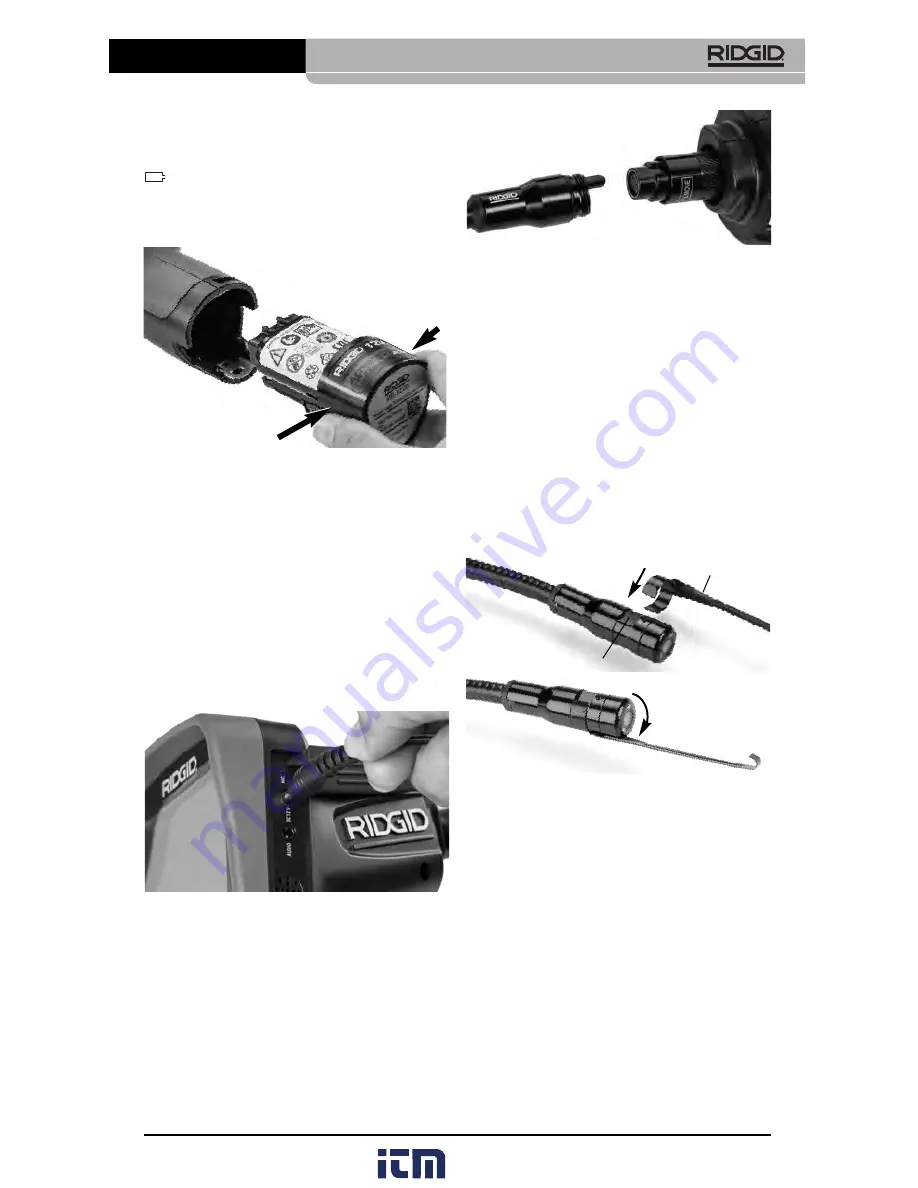
Figure 7 – Cable Connections

3' (90 cm) and 6' (180 cm) cable extensions are
available to increase the length of your camera
cable up to 30 feet (9 m). To install an extension,
first remove the camera head cable from the
display  unit  by  loosening  the  knurled  knob.
Connect the extension to the handheld as de-
scribed above 

(Figure 7)

. Connect the keyed

end of the camera head cable to the slotted end
of the extension and finger tighten the knurled
knob to hold the connection in place.

Installing Accessories

The three included accessories, (Hook, Mag -
net, Mirror) all attach to the imager head the
same way. 

Figure 8 – Installing an Accessory

To connect, hold the imager head as shown in

Figure 8

. Slip the semicircle end of the acces-

sory over the flats of the imager head. Then ro-
tate the accessory a 1/4 turn to retain.

Installing SD™ Card

Open the left side port cover 

(Figure 4)

to ac-

cess the SD card slot. Insert the SD card into
the slot making sure the contacts are facing to-
wards you and the angled portion of the card is
facing down 

(Figure 9)

. SD cards can only be

installed one way – do not force. When an SD
card is installed, a small SD card icon will ap-
pear  in  the  upper  left  hand  portion  of  the
screen, along with the number of images or
length of video that can be stored on the SD
card.

Changing/Installing Batteries

The micro CA-350 is supplied without the bat-
tery installed. If the battery indicator displays

, the battery needs to be recharged. Re -

move the battery prior to storage.

1. Squeeze the battery tabs 

(See Figure 5)

and pull to remove battery.

Figure 5 – Removing/Installing Battery 

2. Insert contact end of battery into the in-

spection tool, as shown in 

Figure 5

.

Powering with the AC Adapter 

The micro CA-350 Inspection Camera can al -
so be powered using the supplied AC Adapter.

1. Open the right side port cover 

(Figure 3).

2. With dry hands, plug the AC adapter into

the outlet. 

3. Insert the AC adapter barrel plug into the

port marked “DC 12V”. 

Figure 6 – Powering the Unit with AC Adapter

Installing the Imager Head
Cable or Extension Cables 

To use the micro CA-350 Inspection Cam er a,
the imager head cable must be connected to
the  handheld  display  unit. To  connect  the
cable to the handheld display unit, make sure
the camera socket key and display unit socket
slot 

(Figure 7)

are properly aligned. Once they

are aligned, finger tighten the knurled knob to
hold the connection in place.

7

micro CA-350 Inspection Camera

Accessory

1/4 Turn

Flats

www.

.com

[email protected]

1.800.561.8187

Содержание micro CA-350

Страница 1: ...micro CA 350 Inspection Camera micro CA 350 Operator s Manual www com information itm com 1 800 561 8187 ...

Страница 2: ...ing with the AC Adapter 7 Installing Imager Head Cable or Extension Cables 7 Installing Accessories 7 Installing SD Card 8 Pre Operation Inspection 8 Tool and Work Area Set Up 8 Operating Instructions 9 Live Screen 10 Image Adjustment 10 Image Capture 11 Menu 11 Time Stamp 12 Language 12 Date Time 12 TV Out 12 Update Firmware 12 Speaker 12 Auto Power Off 12 Factory Reset 12 About 12 Transferring I...

Страница 3: ...etain product serial number which is located on nameplate Serial No WARNING Read this Operator s Manual carefully before using this tool Failure to understand and follow the contents of this manual may result in electri cal shock fire and or serious personal injury www com information itm com 1 800 561 8187 ...

Страница 4: ... and use common sense when operat ing equipment Do not use equipment while you are tired or under the influ ence of drugs alcohol or medication A moment of inattention while operating equipment may result in serious personal injury Do not overreach Keep proper footing and balance at all times This enables better control of the power tool in unex pected situations Use personal protective equipment ...

Страница 5: ...d OFF Any tool that can not be controlled with the switch is dan gerous and must be repaired Disconnect the batteries from the equip ment before making any adjustments changing accessories or storing Such preventive safety measures reduce the risk of injury Store idle equipment out of the reach of children and do not allow persons unfa miliar with the equipment or these in structions to operate th...

Страница 6: ...other substances that may be toxic infectious cause burns or other issues Appropriate personal pro tective equipment always includes safe ty glasses and gloves and may include equipment such as latex or rubber gloves face shields goggles protective clothing respirators and steel toed footwear Practice good hygiene Use hot soapy water to wash hands and other body parts exposed to drain contents aft...

Страница 7: ...h can be determined by turning the equipment OFF and ON the user is encouraged to try to cor rect the interference by one or more of the fol lowing measures Reorient or relocate the receiving antenna Power Supply 12V Li Ion Battery AC Adapter 12V 3 Amp Weight 5 5 lbs 2 5 kg Standard Equipment The micro CA 350 Inspection Camera comes with the following items micro CA 350 Handset 17 mm Imager 3 90 c...

Страница 8: ...Playback Mode Selecting this icon al lows you to view and delete previously saved images and video Menu Push select on this icon to be taken to the menu screen Select Pressing select from the live screen will take you to the playback screen Return Pressing return from the live screen will switch between camera and video Return will also back out of menu and playback mode LED Brightness Press right...

Страница 9: ...ill ap pear in the upper left hand portion of the screen along with the number of images or length of video that can be stored on the SD card Changing Installing Batteries The micro CA 350 is supplied without the bat tery installed If the battery indicator displays the battery needs to be recharged Re move the battery prior to storage 1 Squeeze the battery tabs See Figure 5 and pull to remove batt...

Страница 10: ...crease the risk of electrical shock micro CA 350 Inspection Camera 8 7 Check to make sure the connections be tween the handheld unit extension ca bles and imager cable are tight All con nections must be properly assembled for the cable to be water resistant Confirm unit is properly assembled 8 Check that the warning label is present firmly attached and readable Figure 10 Figure 10 Warning Label 9 ...

Страница 11: ...is water resistant IP54 but should not be submerged in water Determine if any chemicals are pres ent especially in the case of drains It is important to understand the specific safety measures required to work a round any chemicals present Contact the chemical manufacturer for required information Chemicals may damage or degrade the inspection camera Determine the temperature of the area and items...

Страница 12: ...de Selection 3 If the other inspection camera settings Time Stamp Language Date Time TV Out Update Firmware Speaker Micro phone Auto Power OFF Factory Reset need to be adjusted see Menu Section 4 Prepare the camera for inspection The camera cable may need to be pre formed or bent to properly inspect the area Do not try to form bends less than 5 13cm ra dius This can damage cable If inspecting a da...

Страница 13: ...tter button again to stop the video It may take several seconds to save the video if sav ing to the internal memory The micro CA 350 features an integrated mi crophone and speaker for recording and play back of audio with video A headset with inte grated microphone is included and may be used instead of the integrated speaker and microphone Plug the headset into the audio port on the right side of...

Страница 14: ... go black and image will be transmitted to exter nal screen To get live image on unit hit Power button to disable function Update Firmware Select Update Firmware to install the latest version of software on the unit Software will have to be loaded onto a SD Card and in serted into the unit Updates can be found at RIDGID com Speaker Select the Speaker icon in the menu and press Select Select ON or ...

Страница 15: ...r must be used to connect the micro CA 350 Inspection Camera to a Video Out port on the SeeSnake Inspec tion Equipment When connected in this man ner the micro CA 350 Inspection Camera will display the camera view and can be used for recording When connecting to SeeSnake Inspection Equipment microReel microDrain or nano Reel align the interconnect module connected to your reel with the cable conne...

Страница 16: ... CA 350 Inspection Camera Remove the battery before storage or ship ping Service and Repair WARNING Improper service or repair can make the RIDGID micro CA 350 Inspection Camera unsafe to operate Service and repair of the micro CA 350 In spection Camera must be performed by a RIDGID Independent Authorized Service Center For information on your nearest RIDGID In dependent Service Center or any serv...

Страница 17: ...ble regulations Contact your local waste management authority for more information For EC Countries Do not dispose of electrical equipment with house hold waste According to the European Guide line 2012 19 EU for Waste Electrical and Electronic Equipment and its implementation into national legislation elec trical equipment that is no longer usable must be collected separately and disposed of in a...

Страница 18: ...it will not turn ON Troubleshooting Loose cable connections Imager is broken Imager head covered by debris Battery low on power Dead battery Unit need to be reset Check cable connections clean if re quired Re attach Replace the Imager Visually inspect imager head to make certain it is not covered by debris Replace battery with charged battery Replace with charged battery Reset unit See Maintenance...

Отзывы: