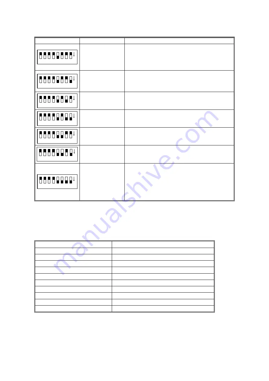
DIP SWITCH SETTINGS
22 December 1998
4-2
Dip Switch
Item
Contents
1
2
3
4
6
7
5
8
ON
ADF counter
indication
The number of pages scanned in ADF mode is
indicated through a combination of the SCSI ID rotary
switch position and the LEDs; refer to Table E later in
this section.
(Unit = 1 sheet, Max. value = 2,500k sheets)
1
2
3
4
6
7
5
8
ON
Book mode counter
indication
The number of pages scanned in book mode is
indicated in the same way as described above for
ADF mode; refer to Table E later in this section.
(Unit = 1 sheet, Max. value = 1,000k sheets)
1
2
3
4
6
7
5
8
ON
Exposure lamp on
time indication
The total illumination time of the lamp is indicated in
the same way as above.
(Unit = 1 hour, Max. value = 3,000 hours)
1
2
3
4
6
7
5
8
ON
CIS on time
indication
The total illumination time of the CIS is indicated in
the same way as above.
1
2
3
4
6
7
5
8
ON
ADF counter
indication
(Reverse side)
The number of pages scanned in ADF mode is
indicated in the same way as above.
(Unit = 1 sheet, Max. value = 2500 k sheets)
1
2
3
4
6
7
5
8
ON
Endorser character
counter indication
The number of endorser characters is indicated in the
same way as above.
1
2
3
4
6
7
5
8
ON
Counter reset mode
After the dip switches are set to on, and the Start
button is held down for more than 3 seconds, all
LEDs are turned off, all counters which are stored in
the E
2
PROM are cleared.
(These counters are the ADF mode, book mode,
exposure lamp, CIS and endorser character
counters.)
NOTE: If you change the position of the SCSI ID rotary switch during these tests,
be sure to put it back to the original position after you have finished.
Table A: Demonstration Mode
SCSI ID Rotary Switch No.
Contents
0
200 dpi scan in book mode
1
400 dpi scan in book mode
2
200 dpi scan in ADF mode
3
400 dpi scan in ADF mode
4
200 dpi scan in endorser mode
5
400 dpi scan in endorser mode
6
200 dpi scan in duplex mode
7
400 dpi scan in duplex mode
8
ADF free run *
1
9
Not used
*
1
: The scanner drives the ADF without any documents.
NOTE: During the demonstration, the LEDs indicate the machine status as usual.
But if an error occurs during the demonstration (e.g. mis-feed, jam, etc.),
the scanner stops, and the LEDs indicate the error condition.


