


4
IQ plus 2100 Installation Manual
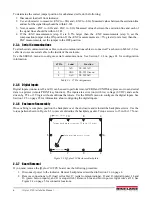
If scale configuration must be changed, see Section 3.0 on page 17 for detailed configuration information. See
Section 4.0 on page 27 for calibration instructions.
2.3
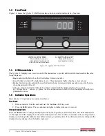
Indicator
The indicator enclosure must be opened to connect cables for load cells, communications and digital inputs.
The IQ plus 210 has no on/off switch. Before opening the unit, ensure the power cord is disconnected
from the power outlet.
• Use a wrist strap to ground yourself and protect components from electrostatic discharge (ESD) when working inside
the indicator enclosure.
• This unit uses double pole/neutral fusing which could create an electric shock hazard. Procedures requiring work inside
the indicator must be performed by qualified service personnel only.
• The supply cord serves as the power disconnect for the IQ plus 210. The power outlet supplying the indicator must be
installed near the unit and be easily accessible.
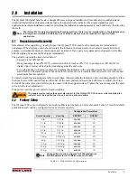
Ensure power to the indicator is disconnected, then remove the screws that hold the backplate to the enclosure
body, then lift the backplate away from the enclosure and set it aside.
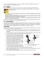
2.3.1
Cable Connections
The
IQ plus 210
provides three cord grips for cabling into the indicator: two for the power cord and load cell
cabling, the third for communications and digital input cables. The free cord grip comes with a plug installed to
prevent moisture from entering the enclosure. If your application requires serial communication or digital input
cabling, remove the plug and install cables as described in Sections 2.3.4 and 2.3.5 on page 6.
Cable Grounding
Except for the power cord, all cables routed through the cord grips should be grounded against the indicator
enclosure. Do the following to ground shielded cables:
•
Use the lock washers, clamps, and kep nuts provided in the parts kit to install grounding clamps on the
studs adjacent to the cord grips. Install grounding clamps only for cord grips that will be used; do not
tighten nuts.
•
Route cables through cord grips and grounding clamps to determine cable lengths required to reach cable
connectors. Mark cables to remove insulation and shield as described below:
•
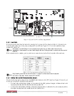
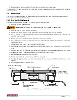
For cables with foil shielding, strip insulation and
foil from the cable 0.5" (15 mm) past the grounding
clamp (see Figure •). Fold the foil shield back on the
cable where the cable passes through the clamp.
Ensure silver (conductive) side of foil is turned
outward for contact with the grounding clamp.
•
For cables with braided shielding, strip cable
insulation and braided shield from a point just past
the grounding clamp. Strip another 0.5" (15 mm) of
insulation
only
to expose the braid where the cable
passes through the clamp (see Figure •).
•
For load cell cables, strip the yellow shield wire
0.75" past the grounding clamp. Fold wire back and
secure between the cable and clamp. Shield wire
function is provided by contact between the cable shield and the grounding clamp.
•
Route stripped cables through cord grips and clamps. Ensure shields contact grounding clamps as shown in
Figure •. Tighten grounding clamp nuts.
•
Finish installation using cable mounts and ties to secure cables inside of indicator enclosure.
WARNING
CAUTION
Cord grip
Insulated cable
Foil
(silver side out)
Grounding clamp
Shield wire
(cut)
Length of foil before folding
back on cable insulation
Cut insulation here
for foil-shielded cables
Braid
Cut insulation here
for braided cables
NOTE: Install lockwashers
first, against enclosure,
under grounding clamp
Figure 2-1. Grounding Clamp Attachment for Foil-
Shielded and Braided Cabling
Содержание IQ plus 2100
Страница 2: ...IQ plus 2100 Digital Bench Scale Version 1 Installation Manual PN 53415 Rev A...
Страница 3: ......
Страница 42: ......


