Rice Lake IQ plus 2100 Скачать руководство пользователя страница 32

Calibration

27

4.0

Calibration

The 

IQ plus 210

 can be calibrated using the front panel, EDP commands, or the Revolution

 configuration utility.

Each method consists of the following steps:

Zero calibration

Entering the test weight value

Span calibration

Optional rezero calibration for test weights using hooks or chains.

The following sections describe the calibration procedure for each of the calibration methods.

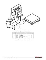
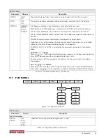
Figure 4-1. Calibration (CALIBR) Menu

4.1

Front Panel Calibration

To calibrate the indicator using the front panel, do the following: 

1. Place the indicator in setup mode (display reads 

CONFIG

) and remove all weight from the scale platform. If

your test weights require hooks or chains, place the hooks or chains on the scale for zero calibration. 

2. Press the 

RIGHT

 (

UNITS

) button until the display reads 

CALIBR

 (see Figure 4-1). Press 

ENTER

 (

ZERO

) to go

to zero calibration (

WZERO

). 

3. With 

WZERO

 displayed, press 

ENTER

 to calibrate zero. The indicator displays 

°CAL°

 while calibration is in

progress. When complete, the A/D count for the zero calibration is displayed. Press 

ENTER

 again to save

the zero calibration value and return to the 

WZERO

 prompt or use the procedure shown in Figure 4-2 to edit

the value. When done, press 

RIGHT

 to go to the 

WVAL

 prompt.

4. With 

WVAL

 displayed, press 

ENTER

 to show the test weight value. If the value is equal to the test weight

you are using, press 

ENTER

 again to save the value and return to the 

WVAL

 prompt; if the value is incorrect,

use the procedure shown in Figure 4-2 to edit the value. When done, press 

RIGHT

 to go to the 

WSPAN

prompt.

When calibrating the indicator with LB/OZ as the primary unit, enter the WVAL value in ounces. For example,
to calibrate a 5 lb scale using LB/OZ, enter 80 (5 lb x 16 oz/lb) as the WVAL value.

5. With 

WSPAN

 displayed, place test weights on the scale then press 

ENTER

 to calibrate span. The indicator

displays 

°CAL°

 while calibration is in progress. When complete, the A/D count for the span calibration is

displayed. Press 

ENTER

 again to save the span calibration value and return to the 

WSPAN

 prompt or use the

procedure shown in Figure 4-2 to edit the value. When done, press 

RIGHT

 to go to the 

REZERO

 prompt.

WZERO

*CAL*

Display and edit

zero calibration

A/D count value

Display and edit

test weight value

WVAL

*CAL*

Display and edit

span calibration

A/D count value

WSPAN

*

CAL*

Press Enter to

remove offset from

zero and span

calibrations

REZERO

XXXXXXX

XXXXXXX

VERS

DEFLT

DIG IN

SERIAL

CALIBR

CONFIG

FORMAT

Note

Содержание IQ plus 2100

Страница 1: ...PRESENTED BY JPBOWLIN COM 817 332 8116 J P Bowlin is a quality driven Calibration Company that has provided calibration repair and sales of all types of weighing and measurement products since 1931...

Страница 2: ...IQ plus 2100 Digital Bench Scale Version 1 Installation Manual PN 53415 Rev A...

Страница 3: ......

Страница 4: ...ptions 21 3 2 1 Configuration Menu 21 3 2 2 Format Menu 22 3 2 3 Calibration Menu 24 3 2 4 Serial Menu 24 3 2 5 Digital Input Menu 25 3 2 6 Default Menu 26 3 2 7 Version Menu 26 4 0 Calibration 27 4 1...

Страница 5: ...33 6 1 1 Displayed Error Messages 33 6 1 2 6 1 2 Using the XE EDP Command 33 6 2 Status Messages 34 6 2 1 6 2 1 Using the P EDP Command 34 6 2 2 6 2 2 Using the ZZ EDP Command 34 6 3 Continuous Output...

Страница 6: ...tches used to zero the scale and select the displayed units Features include Drives up to four 350 load cells Supports 4 and 6 wire load cell connections Two configurable digital inputs Single serial...

Страница 7: ...nnunciators are both lit when the displayed weight is in pounds and ounces 1 5 Indicator Operations Basic IQ plus 210 operations are summarized below Zero Scale 1 Remove material from the scale and wa...

Страница 8: ...ttaching the indicator to the mounting assembly four rubber tilt stand feet for tilt stand option or bench scale feet jam nuts lock washers and cap screws for column and attachment bracket options To...

Страница 9: ...rounded against the indicator enclosure Do the following to ground shielded cables Use the lock washers clamps and kep nuts provided in the parts kit to install grounding clamps on the studs adjacent...

Страница 10: ...ion Jumper The load cell compensation jumper above the ZERO button location on the CPU board see Figure 2 2 must be set for the type of load cell connected to the indicator For load cells with balance...

Страница 11: ...RO and UNITS key presses or to send serial data to a printer remote PRINT key function The inputs are active on with low voltage 0 VDC and can be driven by TTL or 5V logic without additional hardware...

Страница 12: ...im from load cell 5 Turn scale over and unscrew overload protection set screw one full turn 6 Use 7 16 wrench to remove lower load cell screws and lock washers Remove the lower load cell shim load cel...

Страница 13: ...load equal to 125 of scale capacity on the platter Use a hex wrench to advance the set screw until it touches the load cell then back off 1 6 of a turn Verify calibration then add a drop of non perma...

Страница 14: ...and load cell so that no part of the load cell touches the clamshell enclosure Replace lower load cell screws and lock washers Torque to 80 in lb 9 0 N m 3 Install upper clamshell ensuring clearance...

Страница 15: ...37 3 36 Brown Wire Blue Wire From Line Filter 19 1 20 Detail B Ground Post Assembly 16 Back Panel 35 4 To CPU J1 15 27 24 10 11 9 26 From Inside Bottom Panel See Detail A Detail A Inside Bottom Plate...

Страница 16: ...ss screw 1 4 x 28NF x 1 4 1 12 41965 Power cord assembly 115VAC 1 45254 Power cord assembly 230VAC 1 13 41964 Line filter assembly 1 14 14621 Kep nuts 6 32NC hex 5 20 15134 Lock washers internal tooth...

Страница 17: ...12 IQ plus 2100 Installation Manual 2 6 RL2100 Replacement Parts Figure 2 8 RL2100 Repair Parts Illustration 1 2 4 5 9 6 3 7 8 17 19 10 11 12 13 14 15 18 16...

Страница 18: ...le level 1 7 21948 Cap screws 1 4 20NC x 5 8 2 8 15148 Lock washers 1 4 4 9 52341 Overload protection cap screws 10 32NF x 3 4 4 10 39025 Nuts 10 32NF hex 18 8 6 11 15408 Rubber grommet 3 16 ID 1 12 1...

Страница 19: ...igure 2 9 IQ Plus 210 Tilt Stand Assembly Item No Part No Description Qty 1 29635 Tilt stand 1 2 42149 Tilt stand feet 4 3 15144 Nylon washers 1 4x1x1 16 2 4 30342 Wing knobs 2 Table 2 7 IQ Plus 210 T...

Страница 20: ...79 Attachment bracket 1 2 15408 Rubber grommet 3 16 ID 1 3 14956 Cap screws 1 4 20NC x 1 2 2 4 15148 Lock washers 1 4 2 5 14645 Jam nuts 1 4 20NC hex SST 2 6 35128 Bench scale feet 1 4 20NC 2 7 30342...

Страница 21: ...Part No Description Qty 1 52539 12 inch column 1 2 15148 Lock washers 1 4 4 3 14956 Cap screws 1 4 20NC x 1 2 4 4 14645 Jam nuts 1 4 20NC hex SST 4 5 35128 Bench scale feet 1 4 20NC 4 6 30342 Wing kno...

Страница 22: ...ion The Revolution configuration utility provides the preferred method for configuring the IQ plus 210 indicator Revolution runs on a personal computer to set configuration parameters for the indicato...

Страница 23: ...ions of each of the main menus Figure 3 2 Front Panel Key Functions in Setup Mode Front Panel Menu Navigation The front panel buttons are used to navigate through the menus in setup mode see Figure 3...

Страница 24: ...through the values for the parameter Pressing RIGHT from the last value wraps around to first value Press ENTER to select the value and return to the parameter prompt To edit numerical values use the...

Страница 25: ...e and return to the BAUD parameter prompt RIGHT Navigation functions same as BAUD parameter When displaying last parameter prompt press RIGHT to return to the first level menu prompt ENTER ZERO RIGHT...

Страница 26: ...the scale when within the range specified as long as the input is within the configured zero range ZRANGE parameter Selections are display divisions Maximum legal value varies depending on local regul...

Страница 27: ...accurate display by minimizing the effect of a few noisy readings but slows down the settling rate of the indicator Values with the RT suffix provide a raised threshold for filtering larger noise spik...

Страница 28: ...the location of the decimal point or dummy zeroes in the primary unit display Value should be consistent with local legal requirements If LB OZ is selected as the primary unit DECPNT selections are 8...

Страница 29: ...about using this parameter Table 3 4 Calibration Menu Parameters SERIAL Menu Parameter Choices Description BAUD 9600 1200 2400 4800 Baud rate Selects the transmission speed for the serial port BITS 8...

Страница 30: ...one of the XGx EDP commands see Section 5 0 on page 30 If DEMAND AUTO1 or AUTO2 is selected for this parameter serial output is formatted as follows wwwwwww uu GROSS where wwwwww is a 7 digit weight...

Страница 31: ...l the indicator reset and return to the menu level above NOTE All load cell calibration settings are lost when the RESET function is performed Figure 3 11 Default Menu 3 2 7 Version Menu The VERS menu...

Страница 32: ...ERO prompt or use the procedure shown in Figure 4 2 to edit the value When done press RIGHT to go to the WVAL prompt 4 With WVAL displayed press ENTER to show the test weight value If the value is equ...

Страница 33: ...Send the WZERO EDP command to calibrate zero The indicator displays CAL while calibration is in progress 3 Send the WVAL command to enter the test weight value in the following format WVAL nnnnnn CR...

Страница 34: ...omplete the Span Calibration dialog box prompts you to place test weights on the scale for span calibration Place tests weights on the scale then click OK 7 The Rezero dialog box prompts you to remove...

Страница 35: ...y press EDP commands see Table 5 1 simulate pressing the buttons on the front panel of the indicator 5 1 2 Reporting Commands Reporting commands see Table 5 2 send specific information to the EDP port...

Страница 36: ...0D OFF OVRLOAD Overload FS 2 FS 1D FS 9D FS FILTER Digital filtering 1 2 4 8 16 4RT 8RT 16RT Table 5 3 CONFIG EDP Commands Command Description Values PRI DECPNT Primary units decimal position 8 88888...

Страница 37: ...en an indicator is replaced To download configuration data connect the PC to the EDP port as described in Section 5 2 1 Place the indicator in setup mode and use the PC communications software to send...

Страница 38: ...or example the value yyyyy 51807 represents the decimal equivalent of the binary value 1100 1110 0111 1111 Using the bit assignments in Table 6 2 this value indicates all tests were run Error Message...

Страница 39: ...status value see Table 6 3 If more than one annunciator is lit the second number returned is the sum of the values representing the active annunciators For example if the annunciator status value retu...

Страница 40: ...e 6 1 Continuous Output Data Format TERM ASCII 02 decimal Polarity Space Positive Negative Overload Underrange Weight data 7 digits right justified with decimal point leading zero suppression Overload...

Страница 41: ...en odd or no parity Operator Interface Display 6 digit LED display 7 segment 8 in 20 mm digits LED annunciators Negative value center of zero motion kg g lb oz Keypad 2 piezo switches Environmental Op...

Страница 42: ......

Страница 43: ...703 Canada Mexico 800 321 6703 International 715 234 9171 Europe 31 0 26 472 1319 www ricelake com www ricelake mx www ricelake eu www ricelake co in Rice Lake Weighing Systems is an ISO 9001 register...

Отзывы: