


6
IQ plus 2100 Installation Manual
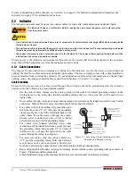
To determine the correct jumper position for unbalanced cells, do the following;
1. Disconnect load cell from indicator.
2. Use an ohmmeter to mEXC to +SIG and +EXC to –SIG. Measured values between the excitation line
and each of the signal lines should be within 2–3
.
3. Next, measure –EXC to +SIG and –EXC to –SIG. Measured values between the excitation line and each of
the signal lines should be within 2–3
.
4. If the +EXC measurements (step 2) are Š 5% larger than the –EXC measurements (step 3), set the
compensation jumper in the ON position. If the +EXC measurements are < 5% greater (or are less) than the –
EXC measurements, set the jumper in the OFF position.
2.3.4
Serial Communications
To attach serial communications cables, connect communications cables to connector J7 as shown in Table 2-3. Use
cable ties to secure serial cable to the inside of the enclosure.
Use the SERIAL menu to configure serial communications. See Section 3.2.4 on page 24 for configuration
information.
2.3.5
Digital Inputs
Digital inputs (connectors J2 and J3) can be used to perform remote ZERO and UNITS key presses or to send serial
data to a printer (remote PRINT key function). The inputs are active (on) with low voltage (0 VDC) and can be
driven by TTL or 5V logic without additional hardware. Use the DIG IN menu to configure the digital inputs. See
Section 3.2.5 on page 25 for information about configuring the digital inputs.
2.3.6
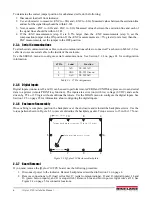
Enclosure Reassembly
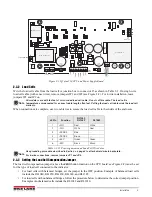
Once cabling is complete, position the backplate over the enclosure and reinstall the backplate screws. Use the
torque pattern shown in Figure 2-3 to prevent distorting the backplate gasket. Torque screws to 15 in-lb (1.7 N-m).
Figure 2-3. IQ plus 210 Enclosure Backplate
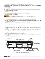
2.3.7
Board Removal
If you must remove the
IQ plus 210
CPU board, use the following procedure:
1. Disconnect power to the indicator. Remove backplate as described in Section 2.3 on page 4.
2. Remove connections to J5 (load cell cable), J7 (serial communications), J2 and J3 (digital inputs), J4 and
J6 (piezo button inputs), and J1 (setup switch). Remove blue and brown power input wires at J8. See
Figure 2-2 on page 5 for connector locations.
J7 Pin
Label
Function
1
TxD
RS-232 TxD
2
GND
RS-232 Ground
3
RxD
RS-232 RxD
Table 2-3. J7 Pin Assignments
S e t u p s w i t c h a c c e s s s c r e w
Fillister head screws
10
9
8
7
4
3
1
2
5
6
To r q u e b a c k p l a t e s c r e w s t o 1 5 i n - l b ( 1 . 7 N - m )
To r q u e p a t t e r n
Содержание IQ plus 2100
Страница 2: ...IQ plus 2100 Digital Bench Scale Version 1 Installation Manual PN 53415 Rev A...
Страница 3: ......
Страница 42: ......


