background image


Installation


3


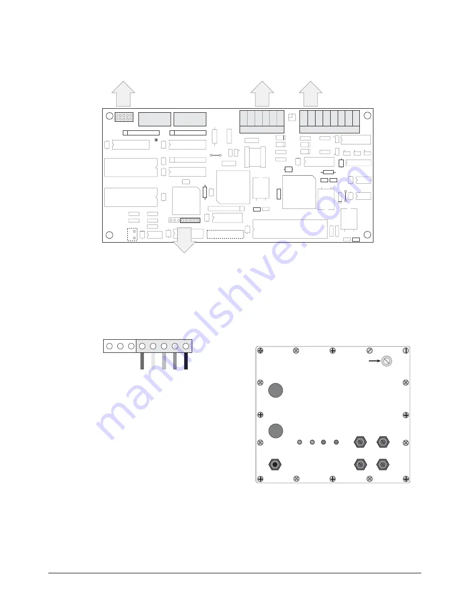
Figure 2-1. Remote I/O Interface Board


16. Plug LED annunciator cable plug into

connector J3 on the Remote I/O Interface
board. Ensure the black wire of the 5-pin
cable plug is attached to pin 1 on the J3
connector (see Figure 2-2). 


Figure 2-2. LED Cable Plug on J3 Connector


17. Feed Allen-Bradley network cable through

cord grip. Allow enough cable for routing
along inside of enclosure to J5 connector on
the Remote I/O Interface board. Connect
Allen-Bradley network cables into connector
J5 on the Remote I/O Interface board as
described in Section 2.2.4 on page 6.

18. Use three cable ties to secure the LED and

Allen-Bradley network cables to the cable tie
mounts attached in step 9.

19. Set termination resistance (jumper JU-1) as

described in Section 2.2.2 on page 6.

20. Set DIP switches as described in Section 2.3

on page 7.


2.1.4

 Reassemble Enclosure


21. Position the backplate over the enclosure and

reinstall the backplate screws. Use the torque
pattern shown in Figure 2-3 to prevent
distorting the backplate gasket. Torque screws
to 15 in-lb (1.7 N-m).


Figure 2-3. IQ plus 510/710/Remote I/O Backplate

C11

C10

R6

R5

X2

X3

U7

C20

D1

U15

C6

C26

C25

C15

C14

C13

C12

U9

C16

1

J4

R11

R17

D2

D3

R12

R14

D4

D5

T1

1

J6

J5

1

R18

R13

C28

C27

U13

C9

C8

U14

C23

C4

X1

U10

C18

U16

U17

C17

J2

C19

U1

C29

JU1

SW1

SW2

1

1

RSIP2

RSIP1

RSIP3

U12

J1

C24

U11

C7

C5

C3

U6

U2

C1

C22

U5

C2

U4

R8

R7

R16

R3

R1

U3

J3

C21

R15

R9

2

3

1

P / N

R10

1

2

10

9

LED CONNECTOR

1

82

150

3

2

4

U8

C30

R4

R2

GND

GND

5V TEST

1

1

1

1

RS-232 TxD

RS-232 RxD

RS-232 GND

N/C

20mA +IN

20mA –IN

20mA +OUT

20mA –OUT

CLEAR

BLUE

SHIELD

CLEAR

BLUE

SHIELD

RESET

Power supply connection to
J15 on indicator CPU board

Allen-Bradley Network

connections

Indicator connections
to J4 on indicator CPU board

DIP switches

Backplate LED connections

J3

LED CONNECTOR

1

BLACK

GREEN

RED

YELLOW

ORANGE

S e t u p   s w i t c h   a c c e s s   s c r e w

Fillister head screws

1

To r q u e   b a c k p l a t e   s c r e w s

t o   1 0   i n - l b   ( 1 . 1 3   N - m )

2

3

4

5

6

7

8

9

10

11

16

12

13

14

15

TxD

RxD

RIO

POWER

DISCONTINUED

Содержание ALLEN-BRADLEY Remote I/O Interface

Страница 1: ...45775 Remote I O ALLEN BRADLEY Remote I O Interface for IQ plus 510 and IQ plus 710 Indicators Version 2 04 Installation and Programming Manual D I S C O N T I N U E D...

Страница 2: ...D I S C O N T I N U E D...

Страница 3: ...s 11 3 1 Output Image Table Format 11 3 2 Input Image Table Format 14 3 3 Bit Shifting 15 4 0 Block Transfer Commands 16 4 1 Set Tare Value 17 4 2 Set Setpoint Values 18 4 3 Read Setpoint Values 20 4...

Страница 4: ...ii Remote I O Installation and Programming Manual D I S C O N T I N U E D...

Страница 5: ...evice to the master PLC appearing as a quarter rack of I O The PLC controller and Remote I O Interface communicate using a quarter rack of data slots 4 slots with 8 bits of input 8 bits of output per...

Страница 6: ...d ground wires to enclosure ground stud 7 Reconnect load cell digital I O and communications cables to the appropriate connectors on the indicator CPU board 2 1 2 Install Remote I O Interface Board 8...

Страница 7: ...nd reinstall the backplate screws Use the torque pattern shown in Figure 2 3 to prevent distorting the backplate gasket Torque screws to 15 in lb 1 7 N m Figure 2 3 IQ plus 510 710 Remote I O Backplat...

Страница 8: ...NC x 1 4 machine screws 4 Standoffs pin 1 Mounting brackets with 6 32NC kep nuts 2 J4 J4 J15 J1 pin 1 J3 Remote I O Interface board Ribbon cable from connector J1 to J15 on indicator board LED connect...

Страница 9: ...or J4 to connector J4 on the Remote I O board Once wiring and DIP switch configuration see Section 2 3 are complete position the backplate over the indicator enclosure and reinstall the backplate scre...

Страница 10: ...ntroller board see Figure 2 1 on page 3 for board location of J4 Figure 2 6 shows the J4 connector layout for the Remote I O Interface Table 2 1 on page 2 shows connections between the Remote I O Inte...

Страница 11: ...F and SW2 7 ON Block Transfer Set SW2 6 ON to enable or OFF to disable block transfer to the Remote I O Interface Setting this switch OFF causes the Remote I O Interface to ignore unsolicited block tr...

Страница 12: ...FF ON OFF 11 13 OFF OFF ON OFF ON ON 43 53 OFF OFF ON OFF ON OFF 12 14 ON ON OFF OFF ON ON 44 54 ON ON OFF OFF ON OFF 13 15 OFF ON OFF OFF ON ON 45 55 OFF ON OFF OFF ON OFF 14 16 ON OFF OFF OFF ON ON...

Страница 13: ...ng RIO Green On steady when communicating with the PLC Blinks if node adapter is receiving only RESET commands from PLC Check if PLC is in program mode Off indicates no connection to the network Check...

Страница 14: ...to the PLC For example a value of 750 1 displayed on the indicator is returned to the PLC as 7501 Block Transfer Block transfer commands support decimal point information with no special handling Pol...

Страница 15: ...32 767 Status Data Format The status data format bits specify the format of status data returned to the PLC 000 Remote function status data 001 Batch function status data valid only for Command 42 Ba...

Страница 16: ...00 1110 Print Request KPRINT cr 15 0000 1111 Clear KCLR cr 17 0001 0000 Clear Accumulator KDISPACCUM cr KCLR cr KCLR cr IQ plus 710 only 21 0001 0101 Clear Tare KDISPTARE cr KCLR cr KCLR cr IQ plus 71...

Страница 17: ...s 8 10 000 20 bit weight format bit 11 1 Remote function status data format bits 12 14 000 The integer value of the bits set in the example above are the sum of Command number 6 Bit shift 0 Weight for...

Страница 18: ...olarity bit is used to indicate the sign of values returned in 20 bit format This bit is not used for 16 bit values Status Data Status data returned on a discrete read command can be either remote fun...

Страница 19: ...as a sign bit The maximum value that can be returned in 15 bits is 215 1 or 32 767 With bit shifting the maximum value that can be returned is increased to 2n b 1 2b 1 where n is the number of data b...

Страница 20: ...he number of the previous block write command 1 and a response code indicating whether or not the block write command was successful If the command failed the command number returned in the block read...

Страница 21: ...code field are 0 00 Command successful 1 01 Command failed 2 10 Block write command format not valid If the block write command failed the command number returned in word 0 is set negative 1 Table 4 3...

Страница 22: ...ysteresis Value LSW 9 p31 Preact Value p16 Preact Value MSW 10 p15 p00 Preact Value LSW Value Kind Description 0 OFF Setpoint turned off ignored 1 GROSSSP Gross setpoint Trips when the current gross w...

Страница 23: ...e PREACT parameter This parameter is used only if PREACT is set to ON or LEARN See the IQ plus 710 Installation Manual for more information about setpoint configuration 18 CONCUR Allows a digital outp...

Страница 24: ...ed in word 0 is set negative 3 Table 4 9 shows the format of the block read command Table 4 9 Block Read Command 3 Read Setpoint Values Word Bit Number Word Contents 15 14 13 12 11 10 9 8 7 6 5 4 3 2...

Страница 25: ...tor value to the PLC controller If the block write command failed the command number returned in word 0 is set negative 4 Table 4 11 shows the format of the block read command Table 4 11 Block Read Co...

Страница 26: ...s a 2 word tare value to the PLC controller If the block write command failed the command number returned in word 0 is set negative 7 Table 4 13 shows the format of the block read command Table 4 13 B...

Страница 27: ...gross value to the PLC controller If the block write command failed the command number returned in word 0 is set negative 8 Table 4 15 shows the format of the block read command Table 4 15 Block Read...

Страница 28: ...s a 2 word net value to the PLC controller If the block write command failed the command number returned in word 0 is set negative 9 Table 4 17 shows the format of the block read command Table 4 17 Bl...

Страница 29: ...Block write command format not valid If the block write command failed the command number returned in word 0 is set negative 11 Table 4 19 shows the format of the block read command Table 4 19 Block R...

Страница 30: ...e read The response code indicates whether or not the Read Multiple Setpoint Values block write command was successful Possible values for the response code field are 0 00 Command successful 1 01 Comm...

Страница 31: ...Batching State block write command was successful Possible values for the response code field are 0 00 Command successful 1 01 Command failed 2 10 Block write command format not valid If the block wr...

Страница 32: ...e commands to the Remote I O Interface and checks the status bits returned in the input image table to confirm completion of each command This example assumes the Remote I O scanner to be in slot 2 wi...

Страница 33: ...WEIGHT DISPLAY NET WEIGHT CLEAR TARE B3 0 I 2 1 9 B3 1 I 2 1 8 B3 2 I 2 1 8 B3 3 I 2 1 9 TARE SCALE SCALE TARE STATUS DISPLAY GROSS WEIGHT GROSS NET STATUS DISPLAY NET WEIGHT GROSS NET STATUS CLEAR T...

Страница 34: ...8 9 END I 2 1 4 IF BIT 4 OF WORD 1 POLARITY BIT IS SET CHANGE SIGN OF DATA TO NEGATIVE DISCRETE WRITE WEIGHT CONVERSION ROUTINE COPY INPUT IMAGE WORD 1 TO INTEGER FILE COPY INPUT IMAGE WORD 0 TO INTEG...

Страница 35: ...BTR Rack 3 Group 2 Module 0 Ctl Blk N10 0 Data File N11 0 Length 2 Continuous NO BTW Rack 3 Group 2 Module 0 Ctl Blk N10 5 Data File N11 10 Length 2 Continuous NO 2 BTR Rack 3 Group 2 Module 0 Ctl Bl...

Страница 36: ...ONVERT 2 WORD PREACT VALUE TO FLOATING POINT VALUE 1 COP Copy File Source F8 2 Dest N11 15 Length 2 COPY FLOATING POINT BAND VALUE INTO TWO SEPARATE WORDS 2 COP Copy File Source F8 3 Dest N11 17 Lengt...

Страница 37: ...ndicator the connection to the PLC controller or the Remote I O Interface itself The flowchart on the following page provides a diagnostic procedure for troubleshooting the Remote I O Interface using...

Страница 38: ...tion is installed but indicator is not connected TxD LED state FLASHING at 1 sec intervals No response from indicator Check indicator configuration Check DIP switch SW2 5 for correct indicator type NO...

Страница 39: ...ote I O Network Communications Twinaxial cable attachment to networks at 56 6 115 2 or 230 4 Kbps Serial Communications Interface RS 232C 20mA current loop optional Data rate 9600 or 19 2 Kbps ASCII e...

Страница 40: ...ot caused by accident misuse neglect alteration improper installation improper repair or improper testing RLWS shall be the sole judge of all alleged non conformities Such equipment has not been modif...

Отзывы: