TM012 Rheem Electric Water Heaters Service Instructions REV: B
Date of Issue: 03/06
This document is stored and maintained electronically by
Service. All printed copies not bearing this statement in RED are deemed “uncontrolled”
8
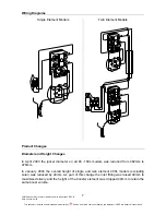
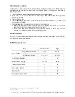
In May 2004 the 111050 (LH connections) and 171050 (RH connections) models were
replaced with the 191050 dual handed model. The dimensions remained unchanged.
In October 2005 the 191050 was superseded by the 191G50 to meet new MEPS
requirements. As part of this change the diameter increased from 393mm to 437mm and
the height increased from 670mm to 673mm
In March 2006 the 191G50 (dual handed) models were superseded by the 111050F (LH
connections) and 171050F (RH connections). The F series 50 litres have a double plus
cylinder allowing for a reduction in diameter from 437mm to 393mm making the unit more
suitable for in cupboard installation. The overall height however increases from 673mm to
690mm.
Element Changes
In November 2005 a new design electric element and cylinder element barrel was
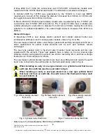
introduced to all Rheem electric storage water heaters (refer to fig. 1A & 1B).
The new design elements utilise a new flange, gasket and earthing arrangement and are a
direct replacement for earlier model elements and as such part numbers remain
unchanged.
The new type gaskets (refer to fig.2) will also fit earlier model elements and are now
supplied with the element. These new gaskets have a radius on the top internal edge
allowing a better seal against the element, are shorter overall by 2mm, and have a flange
thickness of 2.15mm instead of 2.25mm.
The new design cylinder element barrels do not have an earthing tab and require the earth
bond to be connected to the earthing tab on the thermostat clamp (refer to fig. 4).
When installing an early or new type element on a cylinder barrel that has an
earth tab, this earth tab must be used (refer to fig.3).
When installing an early or new type element on a new type cylinder barrel
that does not have an earth tab, the earth tab on the thermostat clamp must
be used (refer to 4).
Fig.1A New design element
front view
Fig.1B New design element
side view
Fig.2 New design element
gasket
Fig.3. Cylinder barrel Earth tab
Fig.4. Thermostat clamp Earth tab
Refer also to Technical Bulletins TB05 019 and TB05 020


