background image

4

WARNINGS

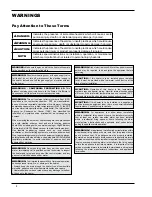
Pay Attention to These Terms

A

DANGER: 

Indicates the presence of immediate hazards which will cause severe 

personal injury, death or substantial property damage if ignored.

A

WARNING:

Indicates the presence of hazards or unsafe practices which could cause 

severe personal injury, death or substantial property damage if ignored.

A

CAUTION:

Indicates the presence of hazards or unsafe practices which could cause 

minor personal injury or product or property damage if ignored.

NOTE:

Indicates special instructions on installation, operation, or maintenance 

which are important but not related to personal injury hazards.

A

DANGER: 

Make sure the gas on which the heater will operate 

is the specified on the heater rating plate.

A

WARNING: 

Should overheating occur or the gas supply valve 

fail to shut, do not turn off or disconnect the electrical supply to 

the heater. Instead, shut off the gas supply at a location external 

to the heater.

E

WARNING - CALIFORNIA PROPOSITION 65: 

This 

product contains chemicals known to the State of California to 

cause cancer, birth defects or other reproductive harm.

A

WARNING: 

This unit contains refractory ceramic fiber (RCF) 

insulation in the combustion chamber. RCF, as manufactured, 

does not contain respirable crystalline silica. However, following 

sustained exposure to very high temperatures (>2192F), the RCF 

can transform into crystalline silica (cristabolite). The International 

Agency  for  Research  on  Cancer  (IARC)  has  classified  the 

inhalation  of  crystalline  silica  (cristabolite)  as  carcinogenic  to 

humans.

When removing the burners or heat exchangers, take precautions 

to avoid creating airborne dust and avoid inhaling airborne 

fibers. When cleaning spills, use wet sweeping or High Efficiency 

Particulate Air (HEPA) filtered vacuum to minimize airborne dust.

Use feasible engineering controls such as local exhaust 

ventilation or dust collecting systems to minimize airborne dust. 

Wear appropriate personal protective equipment including gloves, 

safety glasses with side shields, and appropriate NIOSH certified 

respiratory protection, to avoid inhalation of airborne dust and 

airborne fiber particles.

A

WARNING: 

Do not use this heater if any part has been under 

water.  Immediately  call  a  qualified  service  technician  to  inspect 

the heater and to replace any part of the control system and any 

gas control which has been under water.

A

WARNING: 

To minimize the possibility of improper operation, 

serious personal injury, fire, or damage to the heater:

• Always keep the area around the heater free of combustible 

materials, gasoline, and other flammable liquids and vapors.

• Heater should never be covered or have any blockage to the flow 

of fresh air to the heater.

A

WARNING: 

Risk of electrical shock. More than one disconnect 

switch may be required to de-energize the equipment before 

servicing.

A

WARNING: 

For appliances that allow indoor installation 

within a residential living space or home, the installer must verify 

that at least one carbon monoxide alarm has been installed 

within a residential living space or home following the alarm 

manufacturer’s instructions and applicable local codes before 

putting the appliance into operation.

A

WARNING: 

For appliances that allow indoor installation within 

a residential living space or home, note that this product burns 

gas to produce heat. The appliance must be properly installed, 

operated, and maintained to avoid exposure to appreciable levels 

of carbon monoxide and the installer is required to confirm that at 

least one carbon monoxide alarm is installed in the living space 

before the appliance is put into operation. It is important for the 

carbon monoxide alarms to be installed, maintained, and replaced 

following the alarm manufacturer’s instructions and applicable 

local codes.

A

CAUTION: 

If this heater is to be installed above radiation 

level, it must be provided with a low water cut-off device at the 

time of heater installation.

A

CAUTION: 

Operation of this heater in low temperature 

systems requires special piping. Harmful internal condensation 

will occur if the inlet water temperature does not exceed 105°F. 

Warranty claims will be denied when condensation occurs.

W

CAUTION: 

If this heater is to be installed in a negative or 

positive pressure equipment room, there are special installation 

requirements. Consult factory for details.

Содержание Raypak Delta Limited 399B

Страница 1: ...ns If you cannot reach your gas supplier call the fire department Installation and service must be performed by a qualified installer service agency or the gas supplier This manual should be maintaine...

Страница 2: ...2 Revision 8 reflects the following changes Added two warnings regarding carbon monoxide to Warnings section per ANSI Z21 13_22 Chapters 4 33 1 b and 4 34 i...

Страница 3: ...the Flue Outlet 27 Venting Installation Tips 27 Venting Configurations 28 Outdoor Installation 32 Controls 32 Heater Sequence of Operation 33 Wiring Diagrams 39 START UP 41 Pre Start up 41 Start Up 4...

Страница 4: ...ction to avoid inhalation of airborne dust and airborne fiber particles AWARNING Do not use this heater if any part has been under water Immediately call a qualified service technician to inspect the...

Страница 5: ...ec tive replacement parts will not be accepted and will be replaced in kind only per Raypak s standard warran ties Model Identification The model identification number and heater serial number are fou...

Страница 6: ...ENTER CONTROL COMBUSTION BLOWER IGNITER REMOTE SENSOR BURNER GROUP HEAT EXCHANGER PRESSURE RELIEF VALVE Component Locations Fig 1 Component Locations Back Fig 2 Component Locations Left Side Panels re...

Страница 7: ...356 10 254 2069B 23 5 3 14 356 10 254 2339B 26 5 3 16 406 10 254 Model No Burners per Valve Stages Fire at Stage 1 1A 2 3 4 1 2 3 4 1 2 3 4 399B 8 1 100 499B 5 5 1 1 2 50 100 649B 7 6 1 1 2 54 100 74...

Страница 8: ...r stream and read the thermometer NOTE When this water heater is supplying general purpose hot water for use by individuals a thermostatically controlled mixing valve for reducing point of use water t...

Страница 9: ...ee Fig 4 ACAUTION Hotter water increases the risk of scalding There is a hot water scald potential if the thermostat is set too high Fig 4 Temperature Control Equipment Base The heater should be mount...

Страница 10: ...liance 4 ft 1 2m below or to side of opening 1 ft 30 cm above opening 3 ft 91 cm K Clearance to mechanical air supply inlet 3 ft 91 cm above if within 10 ft 3m horizontally 6 ft 1 83m L Clearance abov...

Страница 11: ...serviced in its installed location without movement or removal of the heater Service clearances less than the minimums may re quire removal of the heater to service either the heat exchanger or the b...

Страница 12: ...Follow these instructions to change the air duct con nection from the left hand side standard to the right hand side 1 Remove the four screws and the dust cover from the right hand side of the heater...

Страница 13: ...all have a minimum free area of a 1 in 2 per 3 000 BTUH 740 mm2 per kW of the total input rating of all equipment located in the enclosure and b Not less than the sum of the areas of all vent connecto...

Страница 14: ...d input of the burner s and the location of the opening s shall not interfere with the intended purpose of the opening s for ventilation air referred to in 1 This opening s can be ducted to a point no...

Страница 15: ...Fig 9 Torque Sequence ACAUTION Damaging internal condensation may occur if the heater inlet water temperature does not exceed 105 F 41 C within 7 minutes of start up Models 399B 899B Models 989B 2339...

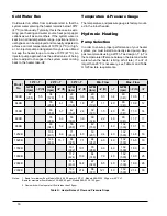
Страница 16: ...The temperature and pressure gauge is factory mount ed in the in out header Hydronic Heating Pump Selection In order to ensure proper performance of your heater system you must install a correctly si...

Страница 17: ...culation of the heater water during the cooling cycle It is highly recommended that the piping be insulated Air Separation Expansion Tank All heaters should be equipped with a properly sized expansion...

Страница 18: ...grains per gallon the operating control must be set no higher than 130F for scale free operation For operating tempera tures above 130F a water softener must be utilized Model No Soft 0 4 grains per...

Страница 19: ...0 5 in WC pressure drop Propane gas 2 500 BTU per ft3 1 53 specific gravity at 0 6 in WC pressure drop Model No 3 4 1 1 1 4 1 1 2 2 2 1 2 3 4 N P N P N P N P N P N P N P N P 399B 15 25 60 100 260 250...

Страница 20: ...o less than 10 pipe diameters of straight smooth pipe downstream of the regulator discharge and to have no less than 10 linear feet not including fittings between the regulator and the inlet to the ap...

Страница 21: ...uivalent Field Connected Controllers It is strongly recommended that all individually pow ered control modules and the heater should be sup plied from the same power source Check the Power Source NOTE...

Страница 22: ...ers instructions 6 Conduit should not be used as the earth ground Field Wiring Connection Fig 19 Wiring Location ADANGER SHOCK HAZARD Make sure electrical power to the heater is disconnect ed to avoid...

Страница 23: ...23 Fig 21 2 Stage Wiring Connections Fig 22 3 Stage Wiring Connections Fig 23 4 Stage Wiring Connection...

Страница 24: ...r example if your heat er is a Model 1529B you will jumper stages two three and four Then your heater will either be on at full fire or it will be off 2 For 2 stage controller connections connect each...

Страница 25: ...vertical runs of vent pipe as necessary Installation in a bull head tee is acceptable as shown in the NFGC The weights on the damper should be adjusted per the damper manufacturer s instructions for p...

Страница 26: ...Wall Venting III Stainless Steel Gas Tight Vertical Natural Draft Venting I B Vent From Outside Building Horizontal Through the Wall Venting III Stainless Steel Gas Tight Galvanized Steel PVC ABS CPV...

Страница 27: ...at least 1 ft above grade including normal snow line 9 Multiple sidewall vent installations require a 4 ft clearance between the ends of vent caps located on the same horizontal plane Changing the Flu...

Страница 28: ...System ACAUTION A listed vent cap terminal ade quately sized must be used to evacuate the flue products from the heaters The maximum and minimum venting length for Cate gory I appliances shall be det...

Страница 29: ...lianc es vented by natural draft shall not be connected into any portion of mechanical draft systems op erating under a positive pressure 1 Seal any unused opening in the common venting system 2 Visua...

Страница 30: ...or B149 Canada CAT III CERTIFIED INSULATED EXHAUST VENTING Fig 27 Horizontal Through the Wall Venting Category III Requires optional vent tee The total length of the horizontal through the wall flue s...

Страница 31: ...t of horizontal run to the vent terminal 2 The vent must be insulated through the length of the horizontal run 3 The horizontal portions of the venting system shall be adequately supported to prevent...

Страница 32: ...he AL29 4C stainless steel vents offered by Heat Fab Inc 800 772 0739 Protech System Inc 800 766 3473 Z Flex 800 654 5600 or American Metal Products 800 423 4270 Pipe joints must be positively sealed...

Страница 33: ...unless the circuit stays energized for more than 5 seconds 11 Power is output from terminal J5 24V of the CPW board to all of the safeties All safeties are verified to ensure that it is safe to opera...

Страница 34: ...is then sent to the 24 VAC safe ty connector 33 24 VAC is now sent to the pressure switch P Switch terminal on the ignition module 34 Once the pressure switch signal is received at the ignition module...

Страница 35: ...VAC power now leaves pin P3 16 of J 5 on the CPW board and is sent to the auto reset high limit optional If closed the power now goes to termi nal P1 4 of J 5 on the CPW board 15 Power is applied to...

Страница 36: ...gas valve and retry the hot surface igniter During ignition retry the heater must per form a 15 second pre purge and an approximate ly 30 second igniter warm up before opening gas valve 1 again The s...

Страница 37: ...the combustion cham ber for about 15 seconds On proof of air flow the air proving switch closes and the igniter is energized To ensure safe operation the gas valve cannot open until the igniter is ver...

Страница 38: ...in WC for propane gas The high gas pressure switch optional connection mounts down stream of the stage 1 gas valve If the gas pressure regulator fails the high gas pressure sheets supplied with your h...

Страница 39: ...39 Wiring Diagram Models 399B 1259B...

Страница 40: ...40 Wiring Diagram Models 1529B 2339B...

Страница 41: ...ilding Immediately call your gas supplier from a neigh bor s telephone Follow the gas supplier s instruc tions AWARNING If you do not follow these instructions exactly a fire or explosion may result c...

Страница 42: ...V transformer or may cause other safety control damage or failure Start Up Blower Adjustment 1 Turn off power 2 Unplug cap at pressure switches and connect ma nometer s to the tee 3 Close all manual f...

Страница 43: ...supervised pilot to light the burner sections on either side of it The burner sections on either side of the supervised section pilot are electrically interlocked with the supervised ignition system s...

Страница 44: ...37 Leak Test This completes leak testing for a single Delta Limited manifold riser Repeat steps 1 8 for each riser Post Start Up Check Check off steps as completed 1 Verify that the heater and heat di...

Страница 45: ...inutes to clear out any gas Then smell for gas especially near the floor If you then smell gas STOP Follow the steps in the safety informa tion on the front cover of this manual If you do not smell ga...

Страница 46: ...5 Outside California 1 800 627 2975 Inside California Replace gas valve Are the gas valve settings correct Replace fan relay Replace fan Replace air pressure switch Correct the air settings or you may...

Страница 47: ...d liq uids 4 Check for and remove any obstruction to the flow of combustion or ventilation air to heater 5 Follow pre start up check in the Start up section 6 Visually inspect burner flame It should b...

Страница 48: ...ct a combustion test at full fire Carbon diox ide should be 7 5 to 8 5 at full fire for natural gas and between 9 2 to 9 8 for propane gas Carbon monoxide should be 150 ppm 5 Check coils for 60 cycle...

Страница 49: ...e In extremely contaminated areas this may also experience deterioration Products causing contaminated combustion air spray cans containing chloro fluorocarbons permanent wave solutions chlorinated wa...

Страница 50: ...899B 1 S 7 S 1 C 2 C 4 C 9 S 13 S 14 S 9 S 1 V 11 M 2 S 6 S 8 S 10 S 9 S 14 S 15 S 13 S 9 S 12 S 11 S 12 M 11 S 1 R 1 M 5 C 2 R 4 M 2 M 6 M 5 G 1 B SEE DETAIL 1 H SEE DETAIL DIAGNOSTIC SEE DETAIL 4 S...

Страница 51: ...51 DIAGNOSTIC DETAIL 12 J 7 J 6 J 5 J 3 0 2 0 16 S 1 F 2 F 3 F 4 F BLOWER DETAIL...

Страница 52: ...52 1 G 5 G 6 G 4 G 2 G 3 G 6 B 13 M 14 M 7 B 4 B 3 B 1 B 5 B 4 M 9 H 2 H 5 H 6 H 1 O 8 H 1 M 5 C 4 H 6 M 3 H 7 H HEAT EXCHANGE DETAIL BURNER ASSEMBLY DETAIL 3 G 4 G 2 G 7 G 8 B...

Страница 53: ...53 13 J 8 J 10 J 11 J 4 J 2 J 3 J 6 C 14 J 9 J 1 J CONTROL BOX DETAILS...

Страница 54: ...007424F 007424F Gas Valve Pro 3 4 Honeywell 601563 007425F 007425F 007425F 007425F 007425F 4 G Switch Low Gas Pressure w o Bracket optional 007187F 007187F 007187F 007187F 007187F 5 G Switch High Gas...

Страница 55: ...007400F 007400F 13 M Touch up Paint Green 750125 750125 750125 750125 750125 Dark Gray 750126 750126 750126 750126 750126 Cool Dark Gray 750256 750256 750256 750256 750256 14 M Sight Window Plug 0084...

Страница 56: ...S Left Right Heat Exchanger Support 010251F 010251F 010251F 010251F 010251F 15 S Support Horizontal 009778F 009779F 009780F 009781F 009782F 16 S Support Assy Controls and Flue Exhaust 009886F 009783F...

Страница 57: ...57 ILLUSTRATED PARTS LIST MODELS 989B 2339B 10 J 3 O 5 O...

Страница 58: ...58 12 H 6 H 7 H 8 H 2 H 9 H 3 H 5 H 1 H 4 H 1 P HEAT EXCHANGER DETAILS BURNER ASSEMBLY DETAILS...

Страница 59: ...59 CONTROL BOX DETAILS 9 J 8 J 23 S 13 J 10 J 3 O 10 J 3 O 5 O FRONT SWITCH DETAILS...

Страница 60: ...6F 010786F 010786F 010786F 010786F 7 C Sensor Water 010787F 010787F 010787F 010787F 010787F 010787F 010787F 8 C Controller RayTemp B 25 010252F 010252F 010252F 010252F 010252F 010252F 010252F 9 C Sens...

Страница 61: ...F 007735F 007736F 007737F 007738F 007738F 007739F Heat Exchange Tube Cupronickel 007740F 007741F 007742F 007743F 007744F 007744F 007745F 7 H Stud Bolt Kit 007828F 007828F 007828F 007828F 007828F 00782...

Страница 62: ...5F 015895F 015895F 015895F 19 M Gas Valve Wire Harness Honeywell 015896F 015896F 015896F 015896F 015896F 015896F 015896F 20 M Power Pump Wire Harness 015898F 015898F 015898F 015898F 015898F 015898F 01...

Страница 63: ...rizontal 009671F 009672F 009673F 009674F 009675F 009675F 009676F 17 S Support Assy Controls and Flue Exhaust 009677F 009677F 009677F 009677F 009677F 009677F 009677F 18 S Flue Collector Top 009678F 009...

Страница 64: ...Manual on your smart device The QR Code will take you to the most current version of the installation manual Previous versions of manuals can be found in the document library at Raypak com P N 241330...

Страница 65: ...additives to water PARTS REPLACEMENT Under this Warranty Raypak will furnish a replacement for any failed part The failed part must first be returned to Raypak if requested with transportation charges...

Страница 66: ...66...

Страница 67: ...67 Raypak Inc 2151 Eastman Avenue Oxnard CA 93030 805 278 5300 Litho in U S A NOTES...

Отзывы: