52
2. Connect a manometer to the pressure tap.
3. Turn on the gas supply and operate the furnace at
100% and all other gas-fired units on the same gas
line as the furnace.
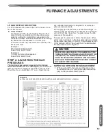
4. Note or adjust the supply-line pressure to give:
A. 5” - 10.5” w.c. for natural gas.
B. 11” - 13” w.c. for LP gas.
If your gas supply does not fall within these ranges,
contact your gas supplier to correct.
5. Shut off the gas at the manual gas valve and remove
the manometer.
6. Replace the supply-line pressure tap plug before turn -
ing on the gas.
7. Check unit for leaks using an approved leak detector.
Do NOT use a flame of any kind.
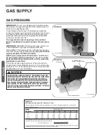
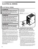
OUTLET/MANIFOLD GAS PRESSURE
MEASUREMENT/ADJUSTMENT
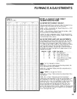
Rate adjustment is a combination of selecting the correct
orifices based on heating value and altitude
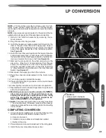
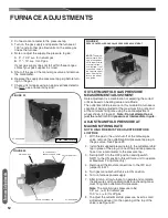
The outlet/manifold pressure on this modulation furnace is
capa ble of being adjusted at the maximum firing rate and
at the minimum firing rate using the same adjustment
wheel shown in Figure 41.
Note: Do not attempt to ad-
just the
outlet/manifold
pressure at intermediate inputs.
ADJUST MANIFOLD PRESSURE AT
MAXIMUM FIRING RATE
NOTE: HIGH FIRE MUST BE ADJUSTED BEFORE
LOW FIRE
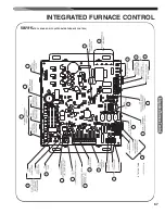
1. With the gas to the unit shut off at the manual gas
valve, remove the outlet/manifold pressure tap plug in
the gas valve. See Figure 39.
2. Install field supplied pressure tap to the outlet/manifold
tap in place of the plug. Connect the positive pressure
hose from a manometer to the pressure tap.
3. Set dip SW10 to the OFF position and dipswitch
SW11 to the ON position (this will force unit to operate
at Maximum Firing Rate only)
4. Remove all thermostat connections to the IFC and
jumper R to W1.
5. Turn gas manual shutoff valve to ON position.
6. Turn on furnace power supply.
7. After ignition, allow furnace to operate and complete
the pressure switch calibration before checking maxi -
mum firing rate outlet/manifold pressure.
Note
: The manifold gas pressure to be:
3.5” w.c. (±.3) for natural gas.
10.0” w.c. (±.5) for LP gas.
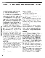
8. To adjust the outlet/manifold pressure, insert a small
slotted screwdriver into the opening at the top of the
valve (see Figure 41).
FURNACE ADJUSTMENTS
Fu
rn
ac
e
Ad
ju
stm
en
ts
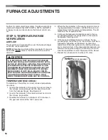
FIGURE 41
SERVO CONTROLLED GAS VALVE PRESSURE ADJUSTMENT
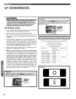
NOTE:
The adjust-
ment wheel will not
stop rotating when
it hits the maximum
or minimum posi-
tion. Instead, it will
continue to rotate to
the opposite adjust-
ment. Use the let-
ters on the wheel
as a guide.
FIGURE 39
OUTLET / MANIFOLD TAP
ST-A1194-88-00
ST-A1194-88-00
ST-A1194-89-00
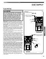
SUPPLY PRESSURE TAP
OFF/ON SWITCH
LP JUMPER WELL
(INSERT JUMPER HERE)
ADJUSTMENT WELL
ST-A1194-89-00
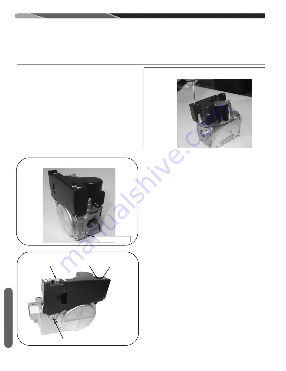
FIGURE 40
Содержание 97MDV060 Series
Страница 91: ...91 TIMING DIAGRAM TABLE 17 TIMING DIAGRAM FOR NON CALIBRATION GAS HEAT SEQUENCE Timing Diagram...
Страница 98: ...98 Diagnostics TABLE 19 continued R97V FAULT CODES WITH DESCRIPTIONS AND SOLUTIONS...
Страница 108: ...108 FIGURE 65 MODULATING ECM FURNACE WIRING DIAGRAM Troubleshooting CM 0716...


