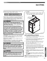
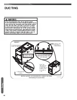
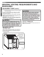
B. USING OUTDOOR AIR FOR COMBUSTION:
IMPORTANT:
Do not take air from an attic space that is
equipped with power ventilation.
The confined space must communicate with the outdoors in
accordance with Methods 1 or 2 below. The minimum dimen-
sion of air openings shall not be less than 3 inches. Where
ducts are used, they shall be of the same cross-sectional
area as the free area of the openings to which they connect.
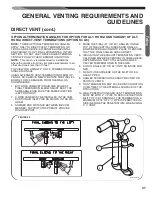
METHOD 1:
Two permanent openings, one located within 12 inches of the
top and one located within 12 inches of the bottom of the
enclosure, shall be provided. The openings shall communicate
directly, or by ducts, with the outdoors or spaces (crawl or
attic) that freely communicate with the outdoors.
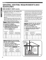
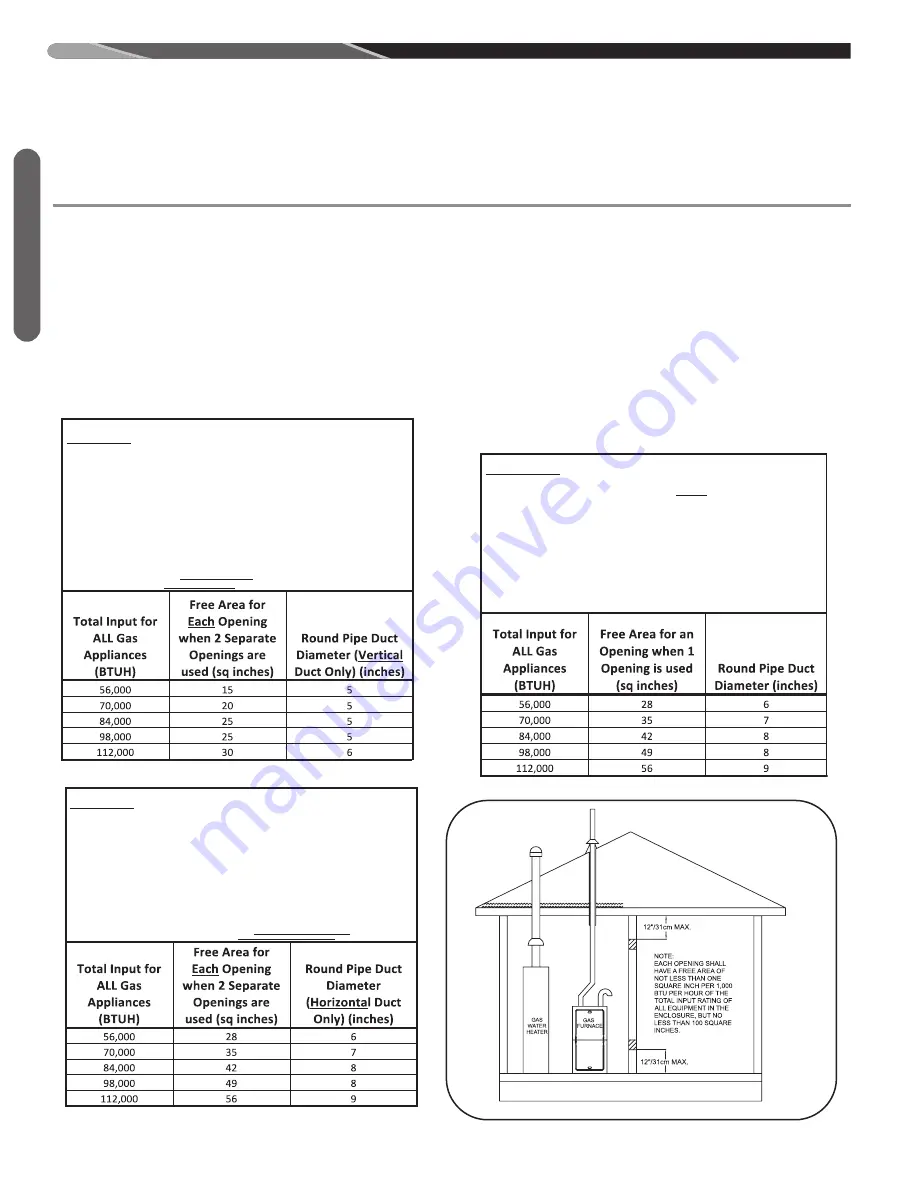
A. Where directly communicating with the outdoors through
an opening or where communicating to the outdoors through
vertical ducts as shown in
Figure 12
, each opening shall have
a minimum free area of 1 square inch for each 4,000 BTUH of
total appliance input rating of all equipment in the enclosure.
Table 8
below specifies the minimum area for each of the 2
combustion air openings and minimum round duct diameter
for direct openings and vertical ducting only.
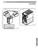
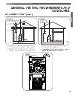
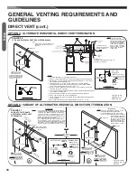
B. Where communicating with the outdoors through horizontal
ducts, each opening shall have a minimum free area of 1
square inch for each 2,000 BTUH of total appliance input rat-
ing of all equipment in the enclosure (see
Figure 13
).
Table 9
specifies the minimum area for each of the 2 combustion air
openings and minimum round duct diameter for horizontal
ducting only.
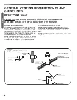
METHOD 2:
One permanent opening located within 12 inches of the top
NON-DIRECT VENT (cont.)
GENERAL VENTING REQUIREMENTS AND
GUIDELINES
ST-A1194-19
FIG C
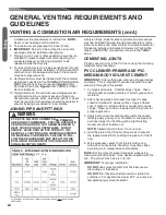
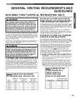
TABLE 8: MINIMUM FREE AREA REQUIRED
FOR EACH OPENING (WHEN TWO OPENINGS
ARE USED) WITH A FURNACE:
1. LOCATED IN A CONFINED SPACE
2. USING OUTDOOR AIR FOR COMBUSTION
3. COMMUNICATING DIRECTLY TO THE
3.
OUTSIDE THROUGH AN OPENING OR
3.
THROUGH A VERTICAL DUCT.
TABLE 9: MINIMUM FREE AREA REQUIRED
FOR EACH OPENING (WHEN TWO OPENINGS
ARE USED) WITH A FURNACE:
1. LOCATED IN A CONFINED SPACE
2. USING OUTDOOR AIR FOR COMBUSTION
3. COMMUNICATING DIRECTLY TO THE
3.
OUTSIDE THROUGH A HORIZONTAL DUCT.
TABLE 10: MINIMUM FREE AREA REQUIRED
FOR AN OPENING (WHEN ONE OPENING IS
USED) WITH A FURNACE:
1. LOCATED IN A CONFINED SPACE
2. USING OUTDOOR AIR FOR COMBUSTION
3. COMMUNICATING DIRECTLY TO THE
3.
OUTSIDE.
Ve
nt
in
g
30
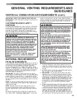
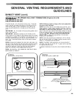
FIGURE 11
NON-DIRECT VENT
AIR FROM
HEATED
SPACE
Содержание 97MDV060 Series
Страница 91: ...91 TIMING DIAGRAM TABLE 17 TIMING DIAGRAM FOR NON CALIBRATION GAS HEAT SEQUENCE Timing Diagram...
Страница 98: ...98 Diagnostics TABLE 19 continued R97V FAULT CODES WITH DESCRIPTIONS AND SOLUTIONS...
Страница 108: ...108 FIGURE 65 MODULATING ECM FURNACE WIRING DIAGRAM Troubleshooting CM 0716...


