39
Ve
ntin
g
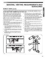
OPTIONS 8 & 9: 2
& 3
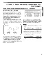
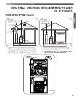
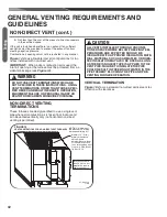
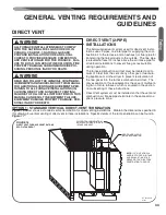
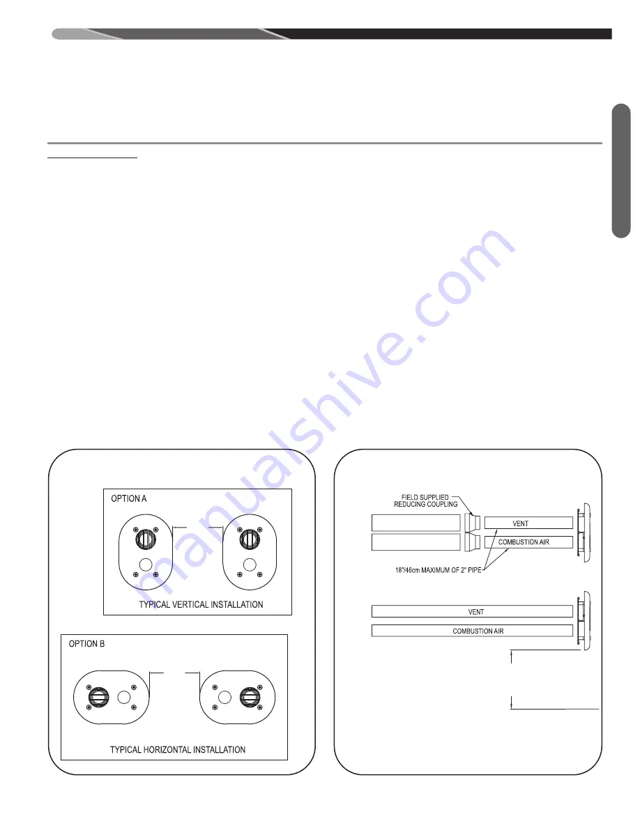
SIDE WALL VENT TERMINATIONS (Figures 24 & 25)
FOR 2
PIPE: RXGY-G02
FOR 3
PIPE: RXGY-G01
DIRECT VENT (cont.)
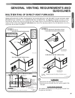
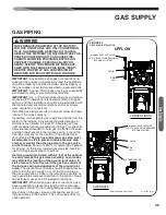
GENERAL VENTING REQUIREMENTS AND
GUIDELINES
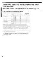
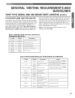
8”
MIN.
8”
MIN.
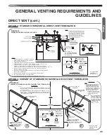
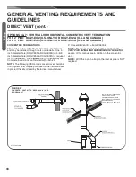
MAINTAIN 12”/31cm FOR THE U.S. AS THE
MINIMUM CLEARANCE ABOVE THE HIGHEST
ANTICIPATED SNOW LEVEL OR GRADE WHICHEVER
IS GREATER. IN CANADA TERMINATIONS MUST CONFORM
TO CSA B149.1-10, SECT. 8.14.
3” PIPE
WITH
OPTIONAL
2” TERMINATION
2” PIPE
(RXGY-G02)
OR
3” PIPE
(RXGY-G01)
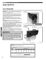
This termination is for horizontal venting only. This termi-
nation may be installed with either a non-direct-vent or a
direct-vent system. When installed as non-direct vent,
only one wall penetration is necessary for the exhaust
vent.
IMPORTANT:
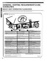
Do not install on the prevailing winter wind
side of the structure.
IMPORTANT:
Maintain a minimum of 12 inches (U.S.)
above grade or the highest anticipated average snow level
(whichever is greater) to the bottom of the vent cover or, in
Canada, terminations must conform with CSA B149.1-10,
Sect. 8.14, Canadian Natural Gas and Propane Installa-
tion Code.
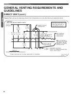
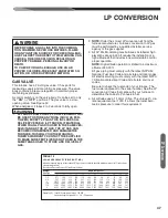
NOTE:
Dimensions between the inlet and outlet pipes (di-
rect-vent only) are fixed by the sidewall termination. Other
drawings in this manual which specify minimum and/or
maximum distances (vertical and horizontal) between
pipes do not apply to the sidewall termination kit.
NOTE:
Multiventing – NO COMMON VENTING IS PER-
MITTED WITH THIS KIT.
NOTE: With this option a trap on the inlet combustion
air pipe is NOT required.
NOTE:
Install the vent and air intake piping into the vent
plate openings. Seal all gaps between the pipes and wall.
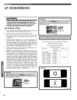
BE SURE TO USE SILICONE SEALANT
to seal the vent
pipe to the vent cap to permit field disassembly for annual
inspection and cleaning. Also seal all pipe penetrations in
the wall.
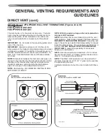
DO NOT INSTALL VENT KITS ONE ABOVE
THE OTHER
to prevent the possibility of condensate
freeze-up or recirculation.
NOTE:
Vent should protrude a maximum of 2-1/4 inches
beyond the vent plate. Air intake should protrude a maxi-
mum of 1 inch beyond the vent plate.
NOTE:
The RXGY-G02 termination can be used with 3”
vent pipe. A maximum of 18” of 2”
pipe can be used be-
fore penetrating the wall.
Complete installation instructions are included with these
kits.
ST-A1194-46
ST-A1194-46
8”
MIN.
8”
MIN.
MAINTAIN 12”/31cm FOR THE U.S. AS THE
MINIMUM CLEARANCE ABOVE THE HIGHEST
ANTICIPATED SNOW LEVEL OR GRADE WHICHEVER
IS GREATER. IN CANADA TERMINATIONS MUST CONFORM
TO CSA B149.1-10, SECT. 8.14.
3” PIPE
WITH
OPTIONAL
2” TERMINATION
2” PIPE
(RXGY-G02)
OR
3” PIPE
(RXGY-G01)
8”
MIN.
8”
MIN.
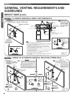
MAINTAIN 12”/31cm FOR THE U.S. AS THE
MINIMUM CLEARANCE ABOVE THE HIGHEST
ANTICIPATED SNOW LEVEL OR GRADE WHICHEVER
IS GREATER. IN CANADA TERMINATIONS MUST CONFORM
TO CSA B149.1-10, SECT. 8.14.
3” PIPE
WITH
OPTIONAL
2” TERMINATION
2” PIPE
(RXGY-G02)
OR
3” PIPE
(RXGY-G01)
FIGURE 25
TYPICAL INSTALLATION – DIRECT VENT
FIGURE 24
VENT KIT INSTALLATION OPTIONS
Содержание 97MDV060 Series
Страница 91: ...91 TIMING DIAGRAM TABLE 17 TIMING DIAGRAM FOR NON CALIBRATION GAS HEAT SEQUENCE Timing Diagram...
Страница 98: ...98 Diagnostics TABLE 19 continued R97V FAULT CODES WITH DESCRIPTIONS AND SOLUTIONS...
Страница 108: ...108 FIGURE 65 MODULATING ECM FURNACE WIRING DIAGRAM Troubleshooting CM 0716...


