Rheem 97MDV060 Series Скачать руководство пользователя страница 1

ISO 9001:2008

INSTALLATION INSTRUCTIONS

FOR UPFLOW CONDENSING MODULATING, 
COMMUNICATING GAS FURNACES W/ECM BLOWER

(-)97V SERIES


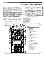
U.L. and/or C.S.A. recognized fuel gas and CO (carbon monoxide) detectors are rec-
ommended in all applications, and their installation should be in accordance with the
manufacturer’s recommendations and/or local laws, rules, regulations, or customs.

92-24161-126-03

SUPERSEDES 92-24161-126-02

Содержание 97MDV060 Series

Страница 1: ...M BLOWER 97V SERIES U L and or C S A recognized fuel gas and CO carbon monoxide detectors are rec ommended in all applications and their installation should be in accordance with the manufacturer s re...

Страница 2: ...s for Alt Horizontal and Variant of Alt Horizontal Direct Vent Terminations Options 4 and 5 37 Option 6 7 Vertical and Horizontal Concentric Vent Termination RXGY E02A and RXGY E03A 38 Options 8 9 Sid...

Страница 3: ...om the distributor and are correct for the installation If not return the unit without open ing the carton If the model number is correct open the carton and verify that the furnace rating label speci...

Страница 4: ...acturer products meet current Federal OSHA Guidelines for safety California Proposition 65 warnings are required for certain products which are not covered by the OSHA standards California s Propositi...

Страница 5: ...ows ______ Exhaust Vent Temperature record temperature TERMINATIONS DIRECT VENT VERTICAL ______ Intake 12 305mm min above roof snow level record height above anticipated snow level or in Canada intake...

Страница 6: ...INSTRUC TIONS WARNING COMBUSTION AND VENTILATION AIR MUST BE PRO VIDED TO THE FURNACE AS REQUIRED BY THE NA TIONAL FUEL GAS CODE U S AND CSA B149 1 CANADA AND THE COMBUSTION AND VENTILATION AIR SECTIO...

Страница 7: ...MBUSTION RETURN AIR TEMPERATURE MAINTAINED BE TWEEN 55 F 13 C AND 80 F 27 C AND CLEAN FURNACE DUCT WORK AND COMPO NENTS UPON SUBSTANTIAL COMPLETION OF THE CONSTRUCTION PROCESS AND VERIFY THAT THE FURN...

Страница 8: ...height of eight 8 feet above grade directly in line with the exhaust vent terminal for the horizontally vented gas fueled heating appliance or equipment The sign shall read in print size no less than...

Страница 9: ...m freezing as required by local practices or codes A UL or CSA listed heat tape or UL or CSA approved heating cable with a rating of 3 6 watts per foot is acceptable pro tection when installed and mai...

Страница 10: ...tion clear ances GENERAL INFORMATION cont FIGURE 4 6 8 OPTION A 2 PIPE OPTION B 2 3 PIPE C ST A1194 86 00 CLEARANCE FLUE VENT TO WALL WARNING DO NOT LIFT THE UNIT BY THE HEAT EXCHANGER TUBES DOING SO...

Страница 11: ...T AIR INLET CONDENSATE DRAIN UPFLOW ELECTRICAL CONNECTION LINE VOLTAGE ELECTRICAL CONNECTION LOW VOLTAGE 22 96 23 80 8 00 11 00 17 44 29 05 26 17 32 88 23 00 14 00 28 06 1 12 29 62 62 19 83 OPTIONAL L...

Страница 12: ...EQUIRES A ROTATION A MINIMUM OF 10 FROM HORIZONTAL AS SHOWN HORIZONTAL INSTALLATIONS REQUIRE CONDENSATE TRAP TO BE MOUNTED EXTERNALLY BELOW THE UNIT USE CAUTION MOUNT THE TRAP AFTER THE UNIT IS AT THE...

Страница 13: ...BULKHEAD COUPLING HOSE DOUBLE ELBOW TUBE C HOSE CLAMP INTAKE AIR DIFFUSER 8 X 1 2 SCREW X4 8 X 1 2 SCREW X10 5 8 DRAIN HOSE B CONDENSATE TRAP BRACKET DOWN FLOW 2 PVC VANE 1 4 HOLE PLUG 1 2 DRAIN HOSE...

Страница 14: ...6 UPFLOW WITH LEFT SIDE VENT Pg 17 18 DOWNFLOW WITH RIGHT VENT NON ZERO CLEARANCE Pg 19 22 DOWNFLOW ZERO CLEARANCE Pg 23 27 HORIZONTAL RIGHT WITH RIGHT VENT Pg 28 30 HORIZONTAL RIGHT WITH VERTICAL VEN...

Страница 15: ...T SIDE REMOVE PLUG DISCARD DRILL 2 1 8 HOLES FOR THE BULKHEAD COUPLING 2 3 OPTION DRAIN LEFT DRILL 1 8 7 8 PLUG DISCARD DRILL 1 8 7 8 PLUG DISCARD INSTALL BULKHEAD COUPLING USING 2 SCREWS INSTALL IN J...

Страница 16: ...PARTS HAVE A SLOPE IN DIRECTION OF WATER FLOW __ BOTH WORM DRIVES ON THE HOSE CLAMPS OF THE IDB COUPLING MUST BE LOCATED ON THE TOP OF THE COUPLING SEE LOCATION DETAIL IN THE GENERAL CONVERSION INSTR...

Страница 17: ...MOVAL 1b REMOVE 3 3 8 FLUSH MOUNT PLUG FROM JACKET DISCARD 1c RELOCATE 2 3 8 FLUSH MOUNT PLUG FROM JACKET TO TOP PLATE 2 2a INSTALL 2 5 8 FLUSH MOUNT PLUG IN TOP PLATE 2b INSTALL 2 PIPE GROMMET AS SHO...

Страница 18: ...UPLINGS ARE TIGHTENED __ ALL DRAIN PORTS ARE PLUGGED __ UNIT HAS FORWARD PITCH __ HEAT TAPE INSTALLED IF REQUIRED 5a LEFT SIDE DRAIN OPTION ATTACH HOSE A PRE INSTALLED TO BULKHEAD COUPLING INSTALL HOS...

Страница 19: ...ating into the living space 6 If a filter is installed near the furnace be sure to have adequate space for installation and removal of the unit filter 7 NOTE Where the maximum airflow is 1800 CFM or m...

Страница 20: ...TIONS INCLUDING CARBON MONOXIDE POISON ING OR DEATH FOR BOTTOM RETURN A SOLID METAL BASE PAN MUST NOT BE INSTALLED FIGURE 7 1 REMOVE BLOWER DOOR AS SHOWN RETAINING TAB DETAIL INSTALLATION OF SOLID ME...

Страница 21: ...LAT INSTALLER BENT UP ALTERNATE BENT DOWN NOTES THIS VIEW IS REPRESENTATIVE OF BOTH SUPPLY AND RETURN OPENINGS DUCT FLANGES MUST BE FIELD BENT ALONG PERFORATIONS EITHER INTO OR OUT OF THE FURNACE AS N...

Страница 22: ...Water softening chemicals De icing salts or chemicals Carbon tetrachloride Halogen type refrigerants Printing inks paint removers varnishes etc Cleaning solvents such as perchloroethyl ene Hydrochlori...

Страница 23: ...erature plastic pipe from another gas or fuel burning appliance unless the re quired minimum clearances to combustibles are main tained between the plastic pipe and other pipes For Canada PVC CPVC and...

Страница 24: ...ction in pres sure drop throughout the system 1 Cut pipe end square Chamfer edge of pipe Clean fitting socket and pipe joint area of all dirt grease and moisture 2 After checking pipe and socket for p...

Страница 25: ...the outside of the structure such as in areas with large accu mulations of snow in winter Table 2 shows the equivalent lengths of different types of elbows Table 3 specifies the equivalent maximum ve...

Страница 26: ...r 3 inch pipe Combinations of long sweep 90s standard 90s or 45s may be used but the manufacturer recommends the use of long sweep 90s whenever possible because the use of the maximum number of standa...

Страница 27: ...Lengths section Table 3 Application of these products is limited to the terminations listed in Ta bles 4 and 5 below These manufacturers have provisions for B vent liners and chimney liners which can...

Страница 28: ...be governed by the following guidelines 1 Avoid terminating under any kind of patio or deck How ever if necessary vent piping may be installed under a deck as long as the termination s is are not und...

Страница 29: ...less than that specified in this table the space is defined as confined If the space is small enough to be designated as confined it must have openings into the space which are located in accor dance...

Страница 30: ...t diameter for direct openings and vertical ducting only B Where communicating with the outdoors through horizontal ducts each opening shall have a minimum free area of 1 square inch for each 2 000 BT...

Страница 31: ...he out doors and shall have a minimum of A 1 Square inch for each 3 000 BTUH of the total input rat ing of all equipment located in the enclosure and NON DIRECT VENT cont GENERAL VENTING REQUIREMENTS...

Страница 32: ...RAL VENTING REQUIREMENTS AND GUIDELINES ST A1194 19 FIG B WARNING DO NOT USE VENT TERMINATIONS WHICH ARE NOT SPECIFIED IN THESE INSTRUCTIONS USING VENT TERMINATIONS OTHER THAN THOSE SPECI FIED HERE CA...

Страница 33: ...LY WITH THE NATIONAL FUEL GAS CODE OR IN CANADA CSA B149 1 NATURAL GAS AND PROPANE INSTALLATION CODE AND LOCAL CODES TO PROVIDE ADEQUATE COMBUSTION AND VENTILATION AIR FOR THE FURNACE FAIL URE TO DO S...

Страница 34: ...inimum only if no snow accumulation is anticipated Venting Terminations more than 24 above roof penetration re quire additional support 12 31cm U S CANADA TERMINATIONS MUST CONFORM TO CSA B149 1 10 SE...

Страница 35: ...E ZONE AS THE EXHAUST TERMINATION 7 NO SCREENS MAY BE USED TO COVER COMBUSTION AIR OR EXHAUST 8 NO T S CAN BE INSTALLED AT THE TERMINATION 9 WALL PENETRATION AND VENT TERMINATIONS MUST BE WITH 2 PIPE...

Страница 36: ...NAL TO THE STRUCTURE MUST BE INSULATED AS REQUIRED FOR LOCAL CLIMATE 10 WALL PENETRATION AND VENT TERMINATION MUST BE WITH 2 PIPE OPTION B ONLY NOTE 1 A TRAP IN THE COMBUSTION AIR PIPE IS NOT REQUIRED...

Страница 37: ...ERMINATION ELBOWS MUST BE AT THE SAME ANGLE AND FACE THE SAME DIRECTION LEFT OR RIGHT 2 A WIND VANE MUST BE INSTALLED IN THE COM BUSTION AIR INLET PIPE AS SHOWN IN THE DIA GRAM 3 NUMBER AND DISTANCE B...

Страница 38: ...hrough roofs or sidewalls One 5 inch diameter hole RXGY E03 RXGY E03A or 3 5 8 inch diameter hole RXGY E02 RXGY E02A is required for the installation See Figure 23 for the general layout Complete inst...

Страница 39: ...sidewall termination kit NOTE Multiventing NO COMMON VENTING IS PER MITTED WITH THIS KIT NOTE With this option a trap on the inlet combustion air pipe is NOT required NOTE Install the vent and air in...

Страница 40: ...0 000 Btuh 30kw 12 30cm 3 ft 9m 10 ft 3 05 m preferred 7 feet 2 1m 3 feet 9m within a height 15 feet 4 5m above the meter regulator assembly 3 feet 9m 6 inches 15cm for appliances 10 000Btuh 3kw 12 in...

Страница 41: ...4 61cm ABOVE ROOF 6 1 8m MINIMUM 10 3m RECOMMENDED A A SEE SEE MINIMUM 12 31cm ABOVE GRADE IN U S 12 31cm U S CANADA TERMINATIONS MUST CONFORM TO CSA B149 1 10 SECT 8 14 48 MAX 122 cm 45 MAX 114 cm 36...

Страница 42: ...it but the furnace will con tinue to run and heat will be provided If the installer uses this approach he must make sure that there is a mechanism for handling the possibility of water overflow onto...

Страница 43: ...SATE WATER SENSOR TO SHUT THE FURNACE DOWN WHEN THE DRAIN IS BLOCKED THIS OPTION WILL NOT SPILL WATER FROM THE DRAIN VENT BUT THE FURNACE WILL ALSO NOT CONTINUE TO RUN WITH A BLOCKED DRAIN CONDENSATE...

Страница 44: ...N AIR AND TENDS TO COLLECT AT LOWER LEVELS MAKING IT MORE DIFFICULT TO SMELL AT NOSE LEVEL NATURAL GAS IS LIGHTER THAN AIR AND WILL RISE POSSIBLY ACCUMULATING IN HIGHER PORTIONS OF THE STRUCTURE IF A...

Страница 45: ...o easily remove the gas valve assembly Local codes may dictate the location of the ground joint union In stall a manual shut off valve in the gas line outside of the furnace casing and upstream of the...

Страница 46: ...ITYTABLE CU FT HR Capacity of gas pipe of different diameters and lengths in cu ft per hr with pressure drop of 0 3 in and specific gravity of 0 60 natural gas Nominal Length of Pipe Feet Iron Pipe Si...

Страница 47: ...al wiring must comply with the latest NFPA 70 National Electrical Code and all state and local codes Be sure to check the fuel code of your furnace The fuel code is adjacent to the serial number See t...

Страница 48: ...pins together inside the jumper well This can be confirmed by visual inspection and by verifying proper manifold pressure at high fire 100 after the jumper is installed Manifold pressure should always...

Страница 49: ...ressure Switch See Figure 37 12 Reconnect the supply gas line to the furnace 13 Place the conversion label adjacent to the A G A rating plate 14 Turn on gas supply and electrical supply 15 Check unit...

Страница 50: ...ng value of 1100 BTU s ft3 at elevations from 0 2 000 ft All other elevations and heating values will require changing orifices and possibly input rate A Gas requirements LP or Natural The furnace is...

Страница 51: ...gas pressure measurements If the supply gas line pressure is above these ranges in stall an in line gas regulator to the furnace for natural gas units With LP gas have the LP supplier reduce the line...

Страница 52: ...s valve remove the outlet manifold pressure tap plug in the gas valve See Figure 39 2 Install field supplied pressure tap to the outlet manifold tap in place of the plug Connect the positive pressure...

Страница 53: ...sure tap plug in the gas valve See Figure 39 2 Install field supplied pressure tap to the outlet manifold tap in place of the plug Connect the positive pressure hose from a manometer to the pressure t...

Страница 54: ...1 Altitude Adjusted Gas Heating Value 975 BTU ft3 given from gas supplier 2 Meter used is 1 revolution per ft3 3 Time per revolution at high fire 36 seconds this is measured by the installer 4 From T...

Страница 55: ...the low end will affect a lin ear adjustment to the entire range of heating airflow ex cept at the 100 rate The adjustment to the range will be such that the 40 heating rate will be adjusted up or dow...

Страница 56: ...he return air temperature from the supply air temperature The dif ference is the temperature rise 5 Compare the measured temperature rise to the ap proved temperature rise range listed on the furnace...

Страница 57: ...EVICE ___AMPERES DISPOSITIF DE PROTECTION CONTRE UNE SURINTENSITE DE ___A AU MAXIMUM NOx EMISSION LIMIT NANOGRAMS JOULE ___ LIMITE D MISSION D OXYDES D AZOTE NOx EN NANORAMMES PAR JOULE ___ HOURLY INP...

Страница 58: ...e re versed Make all electrical connections in accordance with the latest edition of the National Electrical Codes If the line voltage electrical needs to be moved to the op posite side of the furnace...

Страница 59: ...straight against spade terminal This low insertion force flag terminal will deliver an audible click when en gaged Failure to engage will cause defective contact THERMOSTAT The room thermostat must b...

Страница 60: ...Maximum current is 1 0 amps for the electronic air cleaner output HUMIDIFIER Humidifier output is a set of dry contacts The logic control ling these contacts and the necessary wire diagrams for in sta...

Страница 61: ...CREWS TO THE REAR OF THE FURNCE AT THE LOCATIONS PROVIDED UPFLOW HORIZONTAL SIDE RETURN ST A1194 10 X0 ST A1194 11 X0 FIGURE 46 FILTER LOCATIONS ACCESSORIES FIELD INSTALLED OPTION ACCESSORIES cont RXG...

Страница 62: ...e will op erate at 40 heat rate regardless of the heat demand to W1 W2 or V This is done as follows For the single rate mode when dipswitch SW10 is ON and SW11 is OFF the furnace will operate in the 4...

Страница 63: ...alibration Upon proving pressure switches open as noted above the furnace control will energize the inducer at a low starting RPM The furnace control will first verify that the inducer drive is operat...

Страница 64: ...et to level 2 High Pressure Switch Cold Calibration Since the 65 heat inducer RPM is determined or the mid calibration sequence has been skipped for reasons stated the inducer speed is then increased...

Страница 65: ...s valve and deactivation of the ignition means during a trial for ignition period per ANSI Z21 47 definition section Trial for Ignition Period TFI 8 seconds TFI The pe riod of time between energizing...

Страница 66: ...of the 22 second blower on delay period unless the CFM demand of the cir culating airflow is below the threshold specified below Blower Motor Size CFM Cutoff 1 2 HP 500 CFM 3 4 HP 600 CFM Upon provin...

Страница 67: ...67 INTEGRATED FURNACE CONTROL FIGURE 47 FURNACE CONTROL BOARD OR IFC INTEGRATED FURNACE CONTROL ST A1194 73 00 Integrated Furnace Control...

Страница 68: ...n other communicating components are attached and communicating with the furnace control 6 LINE VOLTAGE CONNECTIONS 120VAC L1 Four spade terminals are provided for internal connections and accessories...

Страница 69: ...between the thermostat terminals labeled R and HUM STAT A separate humidistat is not required for this configuration and the humidifier will turn on whenever there is a call for heat and the blower is...

Страница 70: ...is included with EcoNet communicating thermostats To wire the furnace for humidification and de humidification control using an EcoNet communicating thermostat refer to the wiring diagram in Figure 4...

Страница 71: ...UMIDISTAT 24V CONTACTS OPEN WHEN HUMIDITY IS ABOVE SET POINT ST A1194 80 00 SWITCH S2 8 MUST BE IN ON POSITION NOTE FACTORY POSITION IS OFF TURNING THIS SWITCH OFF WILL DISABLE DEHUMIDIFICATION OPERAT...

Страница 72: ...OFF ON 700 CFM 1225 CFM ON ON 525 CFM 1050 CFM LOW COOL SELECTIONS The following CFM s will be used for low stage legacy cooling unless dipswitch SW9 is in the ON position in which case the low cooli...

Страница 73: ...PSWITCHES FIGURE 53 DIPSWITCH MAP NOTE The ECM motor used in a modulating furnace is designed to deliver constant CFM regardless of system static pressure Design system static pressure should never ex...

Страница 74: ...perating at 100 heat rate due to the timed staging algorithm then the IFC will continue to run at 100 heat rate for the rest of the heat cycle regardless of the PWM signal applied to the V W2 terminal...

Страница 75: ...n ter Heat Blower Off Delay SW17 One dipswitch SW17 is to be provided for heat blower off delay selection SW17 Off 90 second SW17 On 120 second Efficiency or Comfort Select SW18 SW 18 will select betw...

Страница 76: ...d be 0 A standard operating code with fault level 0 shall be displayed steady on When displaying a fault code it shall be flashed and not be displayed steady on It shall be flashed on for one second t...

Страница 77: ...this fault several times consecutively When the control enters lockout the fault codes 59 Water Sensed and 10 soft lock out will be displayed alternately as described above A D 11 When IFC is in soft...

Страница 78: ...fault number but has a lower fault level than the new fault then instead of adding the new fault to the buffer the previous fault and level are replaced with the new fault and level The time stamp wil...

Страница 79: ...t most seven segment displays one sec ond on and one second off three times after the fault clear command has been recognized Extended Display Mode If the pushbutton is being pressed during the power...

Страница 80: ...en the terminals is determined to be out of range to a low resistance and a valid thermistor value was sensed on the same power cycle a fault 82 is to be displayed on the seven segment displays If the...

Страница 81: ...le of communicating with a thermostat and condenser to improve cooling and heat pump airflow displaying active faults and active furnace information at the thermostat and improved diagnostics and trou...

Страница 82: ...ommunicating connections Fresh copper must be exposed when making the communicating connections or communications may not be properly established A WIRING OF FULLY COMMUNICATING SYSTEMS Figure 56 is t...

Страница 83: ...83 FIGURE 56 WIRING DIAGRAM FOR A FULLY COMMUNICATING SYSTEM ST A1217 01 THERMOSTAT WIRING DIAGRAMS COMMUNICATING INTEGRATED FURNACE CONTROL Integrated Furnace Control...

Страница 84: ...ON COMMUNICATING THERMOSTAT AND FURNACE WITH NON COMMUNICATING CONDENSER SINGLE STAGE ONLY CONDENSER B WIRING DIAGRAM SPECIAL CONFIGURATION COMMUNICATING THERMOSTAT AND FURNACE WITH NON COMMUNICATING...

Страница 85: ...GURE 55 WIRING DIAGRAM FOR A LEGACY SINGLE STAGE THERMOSTAT WITH AUTOSTAGING SINGLE STAGE THERMOSTAT NON COMMUNICATING TWO STAGE MODULATING GAS FURNACE CONTROL CONDENSER UNIT FIGURE 58 WIRING DIAGRAM...

Страница 86: ...AGRAM FOR A LEGACY TWO STAGE THERMOSTAT TWO STAGE THERMOSTAT NON COMMUNICATING TWO STAGE MODULATING GAS FURNACE CONTROL CONDENSER UNIT FIGURE 59 WIRING DIAGRAM FOR A LEGACY TWO STAGE THERMOSTAT ST A11...

Страница 87: ...ONLY EcoNet COMMUNICATING THERMOSTAT CONTROL CENTER NON COMMUNICATING OUTDOOR UNIT E1 E2 R C D Y1 B R C Y2 SA1 SA2 OAT1 OAT2 S1 S2 S3 HUM HUM EAC L1 NEUTRAL 1 2 R C HUM STAT W1 W2 G Y1 Y2 B O SA1 SA2...

Страница 88: ...QUIRED GURE 58 ING DIAGRAM FOR A LEGACY SINGLE STAGE THERMOSTAT WITH AUTOSTAGING SINGLE STAGE THERMOSTAT NON COMMUNICATING TWO STAGE MODULATING GAS FURNACE CONTROL OUTDOOR UNIT FIGURE 61 WIRING DIAGRA...

Страница 89: ...AC and Ground or Common A fault code 30 is displayed at the furnace control when the fuse has been opened ST A1194 93 01 D 1 2 R C HUM STAT W1 W2 G Y1 Y2 B FIGURE 59 WIRING DIAGRAM FOR A LEGACY 2 STAG...

Страница 90: ...ING DIAGRAM Below are timing diagram for calibration Table 16 and normal heat sequence Table 16 These diagrams assume no faults are present during the heat call TABLE 16 TIMING DIAGRAM FOR A CALIBRATI...

Страница 91: ...91 TIMING DIAGRAM TABLE 17 TIMING DIAGRAM FOR NON CALIBRATION GAS HEAT SEQUENCE Timing Diagram...

Страница 92: ...through it to keep from overheating CAUTION DO NOT OPERATE THE SYSTEM FOR EXTENDED PE RIODS WITHOUT FILTERS A PORTION OF THE DUST ENTRAINED IN THE AIR MAY TEMPORARILY LODGE IN THE AIR DUCT RUNS AND A...

Страница 93: ...ches IMPORTANT It is recommended that at the beginning of the heating season the condensate neutralizer if used be replaced by a qualified installer service agency or the gas supplier IMPORTANT It is...

Страница 94: ...This code indicates that there is a both cooling and dehumidication demand present at the same time When de humidification is active the cooling airflow will be reduced in order to allow water to accu...

Страница 95: ...esent or the SOLUTION Remove the model data card and replace with the original memory card from the furnace or the correct replace CAUSE Typically the model data card will be missing from the furnace...

Страница 96: ...e This fault will not be displayed to the homeowner on communicating systems unless it occurs at least three times within a single heat call It will not be displayed to the homeowner after the first o...

Страница 97: ...purge After both the post purge and blower off delay are complete the fault code 13 is removed and a new attempt at ignition is made Often the new ignition attempt will fail and operation will proceed...

Страница 98: ...98 Diagnostics TABLE 19 continued R97V FAULT CODES WITH DESCRIPTIONS AND SOLUTIONS...

Страница 99: ...that all gaskets between the inducer and center panel heat exchanger are properly installed and sealed 3 Unstable flame pattern CAUSE 2 Loose or faulty wiring SOLUTION 1 Replace low pressure control s...

Страница 100: ...l board inducer relay 5 Loose or faulty wiring 6 Disconnected blocked split or cut pressure switch hoses 45 EXPECTED OPERATION 1 DISPLAYED BEFORE HEAT IS ESTABLISHED The IBM Indoor Blower Motor will n...

Страница 101: ...of P4 at the IFC or at the water sensors is not properly made 7 Replace hoses as necessary 8 Insure proper termination and determine if high altitude kit may be necessary see item 4 2 Check the speci...

Страница 102: ...f operation should operate as normal CAUSE 1 A blocked condensate drain or the drain trap has become blocked and cannot allow condensate water to flow properly 2 Wiring to the sensors has been damaged...

Страница 103: ...ecause the static pressure is too high SOLUTION 1 The static pressure is too high because the ductwork is improperly designed or is restricted for some other reason or the filter needs cleaning or rep...

Страница 104: ...is fault is cleared However this fault may also indicate an internal microprocessor failure This may mean that the heat call will not end as expected and that all outputs will be de energized and gas...

Страница 105: ...con tacts welded relay and will not clear by cycling the in ducer Fault code 93 is set and displayed This lockout condition cannot be reset by cycling the heat call 3 The furnace control will declare...

Страница 106: ...at 75 of capacity If the motor is operating at a good speed it is likely not the motor that is the problem If the motor is not operating verify that the control wiring between the motor and furnace co...

Страница 107: ...ate the motor again If the motor continues to fail it may be perma nently damaged and may need to be replaced B Is the motor overheating If so it may report an overheat condition to the furnace contro...

Страница 108: ...108 FIGURE 65 MODULATING ECM FURNACE WIRING DIAGRAM Troubleshooting CM 0716...

Отзывы: