602400011500
Revision C
Page
13
of
24
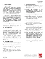
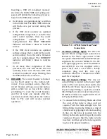
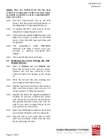
Inserting a USB 2.0 compliant memory
stick into the DATA PORT and cycling unit
power will initiate the following processes
based on the USB stick contents:
In all cases, an operational log is written
to the USB stick. The RUN TIME indicator
will flash once per second during this
process.
If the USB stick contains an updated
configuration image that is valid for the
unit’s serial number, then the unit’s
configuration
settings
will
be
reprogrammed. The HIGH PRESSURE
indicator will blink 5 times to indicate
success.
If the USB stick contains an updated
software image that is valid for the unit’s
serial number, then the unit’s firmware
will be reprogrammed. The HUMIDITY
indicator will blink 5 times to indicate
success.
In all cases, after completion of data
processes, the unit will restart and run
normally. Make sure that the USB stick
read/write indicator stops blinking, then
the USB stick can be removed.
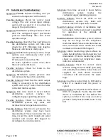
5.4
BREAKER:
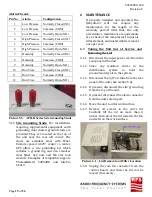
The circuit breaker is located
on the front panel in the bottom left
corner. If an overload occurs, then the
circuit breaker will open and the button
with a white bar on top will be visibly
protruding. To reset the circuit breaker,
wait for at least one minute after the
overload occurred, then press the button
back in. The unit will resume normal
operation.
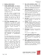
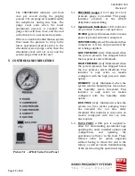
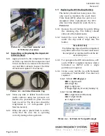
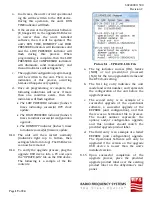
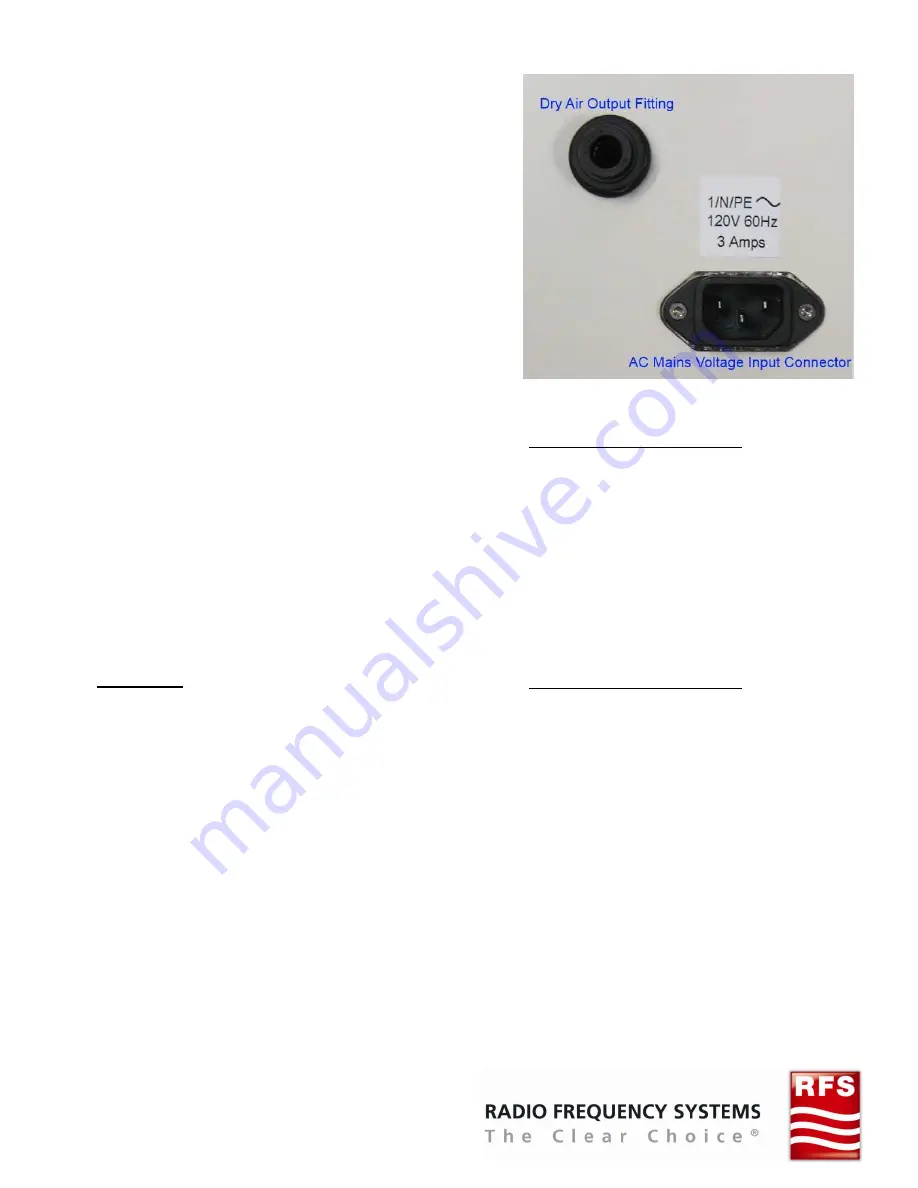
Picture 5.2 – APD-D Series Rear Panel
Connections
5.5
AC
Mains
Voltage
Input:
The IEC C14
type AC Mains voltage input connector is
located in the lower right corner of the
rear panel. The APD20-D and APD70-D are
supplied with a 2 meter NEMA 5-15 to IEC
C13 right angle power cord. The APD22-D
and APD72-D are not supplied with a
power cord, and a cord with a locally
compliant plug and IEC C13 type
connector rated for a minimum of 250V
and 15A is required.
5.6
Dry
Air
Output
Fitting:
The dry air
output fitting is located in the lower right
corner of the rear panel, above and to the
left of the AC Mains input connector. The
dry air output fitting is a push-to-connect
tube fitting that can be reused many times.
All APD-D models are supplied with 10’ of
3/8” polyurethane tube.
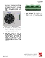
To connect tube to fitting: Make sure that
the end of the tube is clean and cut
square. Push the tube straight into the
fitting firmly. Inside the fitting is a ring of
stainless steel gripping teeth and a sealing
O-ring. As the tube is pushed into the
fitting, both teeth and O-ring will provide
resistance. Ensure that the tube is fully
inserted, and then give the tube a gentile
tug to verify proper insertion.

