background image

19

Installation

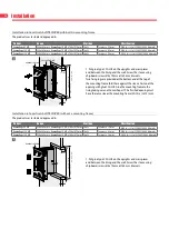
Installation into vertical shaft GLASROC F V500 with built-in mounting frame

The product was tested and approved in:

Product

Range

Wall type

Classification

Kamouflage 60 MP

350x385 mm ≤ Kamouflage 1V MP ≤ 700x1075 mm Shaft

Glasroc F V500 ≥ 35 mm

EI 60 (v

ed

 i 

n

 o) S 1500 C10000 AA multi

Kamouflage 120 MP

350x385 mm ≤ Kamouflage 1V MP ≤ 700x1075 mm Shaft

Glasroc F V500 ≥ 50 mm

EI 120 (v

ed

 i 

n

 o) S 1500 C10000 AA multi

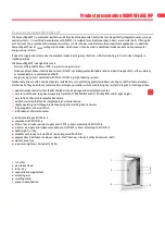
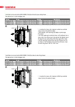
e

≥ 125 mm

KAMOUFLAGE MP

EASY-KAP ME/MP

e

A = 2 x e + 20 mm

(W+
A

) x (H+

A

) mm

(W+
20) x (H+

20) mm

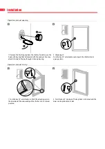
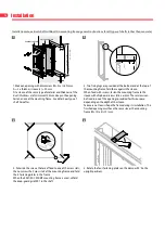
1. Put glue type GLASROC F V500 on the uprights and cross 
pieces and between the lining and the wall. Screw the sleeve 
using chipboard screws Ø5 x 70 mm at 150 mm intervals.  
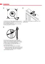
Two fixing lugs are provided at the bottom and at the top of 
the mounting frame: fold these against the sleeve. First coat 
the opening with glue GLASROC F V500. Glue the mounting 
frame to the lining taking care not to misshape it. The finished 
opening must have the same size as the mounting frame 
(W+10) x (H+10) mm.


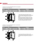
Installation into vertical shaft GLASROC F V500 (without a mounting frame)

The product was tested and approved in:

Product

Range

Wall type

Classification

Kamouflage 60 MP

350x385 mm ≤ Kamouflage 1V MP ≤ 700x1075 mm Shaft

Glasroc F V500 ≥ 35 mm

EI 60 (v

ed

 i 

n

 o) S 1500 C10000 AA multi

Kamouflage 120 MP

350x385 mm ≤ Kamouflage 1V MP ≤ 700x1075 mm Shaft

Glasroc F V500 ≥ 50 mm

EI 120 (v

ed

 i 

n

 o) S 1500 C10000 AA multi

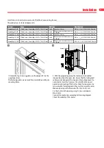
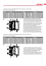
KAMOUFLAGE MP

e

≥ 125 mm

e

A = 2 x e + 10 mm

(W+
A

) x (H+

A

) mm

(W+10) x (H+10) mm

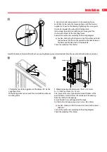
1. Put glue type GLASROC F V500 on the uprights and cross 
pieces and between the lining and the wall. Screw the sleeve 
using chipboard screws Ø5 x 70 mm at 150 mm intervals.

1

1

Содержание Kamouflage 120 MP

Страница 1: ...mbachtstraat 40 9860 Oosterzele Belgium Tel 32 9 362 31 71 Fax 32 9 362 33 07 info rft be 1812 V28 EN A 09 2019 KAMOUFLAGE MP Motorised aesthetic and CE marked smoke control shutter can be perfectly i...

Страница 2: ...on into vertical shaft PROMATECT L500 without a mounting frame 16 Installation into vertical shaft GEOFLAM LIGHT GEOTEC with built in mounting frame 17 Installation into vertical shaft GEOFLAM LIGHT G...

Страница 3: ...t E ALIM power supply motor Auto automatic Tele remote controlled Pnom nominal capacity Pmax maximum capacity DAS MOD modular product OP option delivered with the product KIT kit delivered separately...

Страница 4: ...ry concrete blocks concrete 100 mm Kamouflage 120 MP Shaft Promatect L500 40 mm 1 EI 90 v ed i n o S 1500 C10000 AA multi Geoflam 35 mm Tecniver 45 mm Exthamat 30 mm Desenfire 25 mm THD Concrete 90 mm...

Страница 5: ...rs and dampers are suitable for use in ventilating protected lobbies venting to shafts either naturally or mechanically They open to evacuate smoke in emergency situations whilst maintaining fire resi...

Страница 6: ...sions shutter Wn x Hn 6 Built in dimensions without mounting frame Wn 10 x Hn 10 mm 7 Built in dimensions with mounting frame Wn 20 x Hn 20 mm 8 Overall outside dimensions of the shutter Wn 54 x Hn 54...

Страница 7: ...The installation of the shaft must comply with the classification report delivered by the shaft manufacturer Axis orientation see the declaration of performance Verify if the blade can move freely Rf...

Страница 8: ...key through its handy key ring 20 2 Unlocking 1V Turn the key 20 anti clockwise and push the shutter into its open position Operation manual closing 20 1 Turn the key 20 anti clockwise Push the actua...

Страница 9: ...ix the grommet delivered with the product 1 2 2 2 3 4 4 Lead the cables through the opening Use the protective sleeve 1 the fixation clips 2 and the plastic cable clamp 3 to attach the cables to the f...

Страница 10: ...installed either in the shaft in the axis of the shaft or outside the shaft or shaft extension 90 mm 90 mm 90 mm 125 mm 125 mm 125 mm 3 In order to prevent cracks around the opening in the long term a...

Страница 11: ...ake an opening with dimensions W 20 x H 20 mm In case the mounting frame is fixed with mortar Make an opening with dimensions W 20 x H 20 mm till W 100 x H 100 mm 2 The mounting frame should always be...

Страница 12: ...position it in the mounting frame Fasten the shutter onto the mounting frame with the 4 screws supplied as shown in the drawing Tightening the screws pulls the shutter towards the wall until its final...

Страница 13: ...ge 120 MP 350x385 mm Kamouflage 1V MP 700x1075 mm Shaft Masonry concrete blocks concrete 100 mm EI 120 ved i n o S 1500 C10000 AA multi 1 Rotate the four fastening plates on the damper 90 to the uprig...

Страница 14: ...the top of the mounting frame fold these against the sleeve When fixed with screws fasten the mounting frame to the sleeve with chipboard screws 6 x e mm These screws can be fixed in one of the openi...

Страница 15: ...to vertical shaft without a mounting frame general instructions for all types of shafts other than concrete 1 Rotate the four fastening plates on the damper 90 to the upright position The fastening pl...

Страница 16: ...ng frame to the sleeve with chipboard screw 6 x e mm Two fixing lugs are provided at the bottom and at the top of the mounting frame fold these against the sleeve Seal the mounting frame with Promacol...

Страница 17: ...ese against the sleeve Caulk the mounting frame to the duct with vegetable fibre or in case of Geotec you can also coat the opening with Geocol S and fasten the mounting frame with screws of 5 x e mm...

Страница 18: ...bottom and at the top of the mounting frame fold these against the sleeve First coat the opening with glue CF GLUE Glue the mounting frame to the lining taking care not to misshape it The finished op...

Страница 19: ...tom and at the top of the mounting frame fold these against the sleeve First coat the opening with glue GLASROC F V500 Glue the mounting frame to the lining taking care not to misshape it The finished...

Страница 20: ...d at the bottom and at the top of the mounting frame fold these against the sleeve Caulk the mounting frame to the duct with vegetable fibre and taking care not to misshape it The finished opening mus...

Страница 21: ...ed at the bottom and at the top of the mounting frame fold these against the sleeve Caulk the mounting frame to the duct with vegetable fibre and taking care not to misshape it The finished opening mu...

Страница 22: ...oints of the shaft must be adjusted in proportion to the increased weight The installation of the shaft must comply with the classification report delivered by the shaft manufacturer 40 3 When mountin...

Страница 23: ...est such that each damper within a system is inspected checked and tested at least once in any 6 month period The following instructions are a general guide and our recommendations to the procedures r...

Страница 24: ...h the installation guidelines press the drive linkage arm to unlock position and pull the damper closed motorised resetting remote controlled by reversing 2 wire control or alternating 3 wire control...

Страница 25: ...2 1075 kg 21 6 23 5 25 3 27 0 27 3 28 9 30 5 34 1 Selection data p 0 6 v KAMOUFLAGE MP 1V60 1V120 Hn Wn mm 350 400 450 500 550 600 650 700 385 3 860 3 158 2 677 2 329 2 063 1 856 1 688 1 550 415 3 46...

Страница 26: ...0 0 2780 0 3160 0 3540 0 3930 0 4310 0 4690 0 5080 835 Sn m 0 2490 0 2890 0 3280 0 3680 0 4080 0 4480 0 4880 0 5280 865 Sn m 0 2580 0 2990 0 3410 0 3820 0 4230 0 4650 0 5060 0 5470 895 Sn m 0 2670 0 3...

Отзывы: