RF Code R151 Скачать руководство пользователя страница 9

Re

co

m

m

en

de

d B

es

t Pr

ac

tic

es

9

PN01805 REV00

Tem

p. Sensor Connection

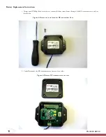
5.  Determine proper position and placement for the R151 Tethered Temperature Sensor mounting. Keep in mind 

that the temperature sensor tether cable will need to be reattached to the adhesive and its positioning should not 

cause strain on the tag nor the tether. Remove the paper backing from the tag and press firmly for ten seconds to 

mount it into place (or optionally secure by using mechanical fasteners or tie-wraps).

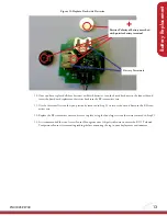
6.  Slide the exposed cable ends back into the tether connector, paying close attention to the proper polarity. The 

Red


cable wire should be positioned in the left (

+

) terminal and the 

Black

 cable wire should be positioned in 

the right (

-

) terminal (See image below). Tighten the terminal connector screws down to make contact with the 

temperature sensor tether cable wires using a size 2 or smaller Flat head screwdriver.


 Take care to avoid twisting and fraying the end of the exposed wires when tightening the terminal 

connectors. Doing so can cause connection issues and cable damage.

Figure 4: R151 Temperature Sensor Tether Cable Wire Attachment

Recommended Best Practices

The RF Transmitter should be mounted four feet or more above the floor to enable the best possible read range.

RF fields of active tags are affected by large metal surfaces. Adhering tags directly onto metal surfaces may result in 

diminished read range and therefore should be avoided if possible.

!

+

 Red wire

-

Black wire

Polarity Indicators

Содержание R151

Страница 1: ...discover track monitor Installation Guide R151 Tethered Temperature Sensor...

Страница 2: ...rature Sensor 5 Introduction 5 Features 5 Contents 5 Hardware 6 RF Transmitter Operational Specifications 6 Power Specifications 6 Installation Steps 7 Temperature Sensor Tether Cable Connection Steps...

Страница 3: ...ny errors or inaccuracies that may appear in these pages RF Code reserves the right to make changes without further notice to any products herein RF Code makes no war ranty representation or guarantee...

Страница 4: ...The system is designed to operate with RF Code RFID Tags whose operating frequency is 433 92 MHz which have been certified or are in the certification process These devices comply with part 15 of the...

Страница 5: ...ng with the ambient temperature measured by the temperature sensor every 20 seconds RF Code s Environmental Monitoring solution line is made up of R120 Door Tag R130 Dry Contact Tag R135 Fluid Detecto...

Страница 6: ...tter storage temperature limits however the battery life is optimized at 5 years for normal use in temperature controlled environments between 50 F and 130 F If the RF transmitter is subject to prolon...

Страница 7: ...ment of the cable is minimized Once the R151 Tethered Temperature Sensor has been properly installed it can be configured within RF Code s Sen sor Manager software where users can view tag details use...

Страница 8: ...ure 2 Temperature Sensor Tether Cable Connector Terminal Figure 3 Temperature Sensor Tether Cable Detached 3 Place the temperature sensor tether cable in the environment in which you desire to monitor...

Страница 9: ...left terminal and the Black cable wire should be positioned in the right terminal See image below Tighten the terminal connector screws down to make contact with the temperature sensor tether cable wi...

Страница 10: ...Phillips head screw driver remove the four screws from the top of the RF transmitter case and set them aside Figure 5 Remove screws from the RF transmitter Case 2 Carefully remove the RF transmitter c...

Страница 11: ...board in place 4 Remove the board from the RF transmitter case 5 Remove the first battery located on the front side of the board from the battery holder Figure 8 Remove battery 6 Replace the front sid...

Страница 12: ...terminals Figure 9 Batteries and Battery Terminals on back side of board 8 Remove the batteries from their terminals Figure 10 Remove Batteries from back side of board 9 Replace the back side batterie...

Страница 13: ...you previously removed in Step 3 to secure the circuit board to the RF trans mitter case 12 Replace the RF transmitter cover and secure in place using the four larger screws that were removed in Step...

Страница 14: ...g usage or trade practice Obtaining Service Support For in warranty service customers have several options Customers having difficulty with RF Code products should attempt to solve those problems thro...

Страница 15: ...discover track monitor...

Отзывы: