Reznor OH Скачать руководство пользователя страница 33

I-OH (01-20) PN120390R7

33

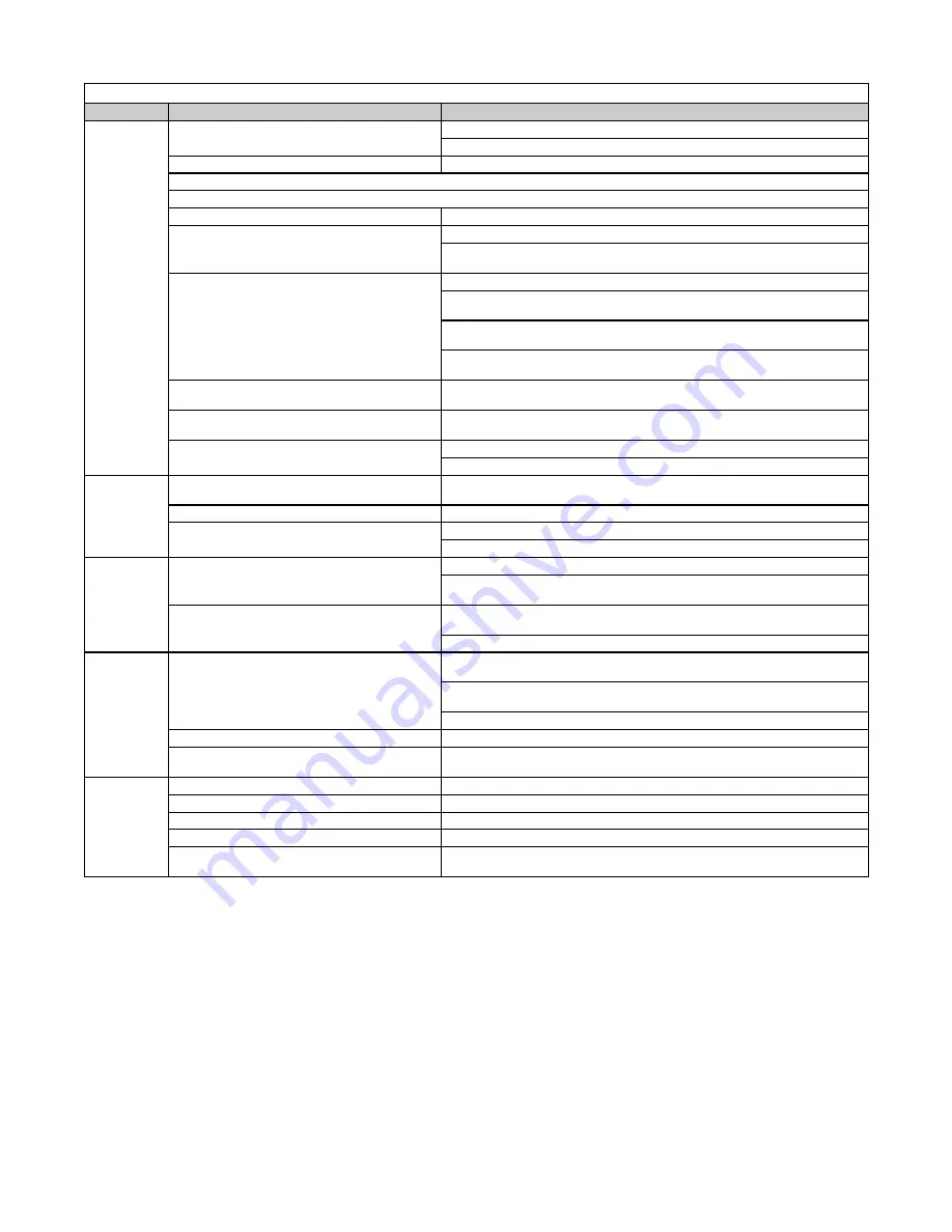
Table 14.  Oil Burner Troubleshooting

Symptom

Probable Cause

Remedy

Burner motor 

operates and 

delivers oil 

but there is 

no flame

1.  No spark

Check transformer, insulators, and electrodes
Transformer/ignition problems may be due to following causes:


a)  Excessive gap on ignition electrodes

Ensure that gap is 1/8 inch


b)  High ambient temperatures


c)  High humidity


d)  Carbon residue on the porcelain bushings Clean porcelain bushings


e)  Low input line voltage

Measure voltage between transformer/primary lead and neutral connection

NOTE: The secondary terminals of a good transformer deliver 5000V 

arc to ground for a total of 10,000V between the terminals.


f)  Arcing between ignition electrodes and 


transformer springs

Ensure that ignition electrodes and transformer springs have good contact
Measure arc with transformer tester or use well-insulated screwdriver to 

draw arc across two springs; ensure that arc is at least 3/4 inch long
Check each secondary output terminal by drawing strong arc between 

spring and base
If arc is erratic, weak, or unbalanced between two terminals, replace 

transformer

   g)  Carbon residue, moisture, crazing, or pin 

       holes on insulators

Clean any carbon residue and replace any insulators that are questionable

   h)  Improper positioning of nozzle in relation 

       to radius of endcone

Check and correct nozzle position as necessary

   i)   Carbon residue on electrode parts

Clean any carbon residue
Replace electrodes when tips become worn or eroded

Burner starts 

but flame 

blows away 

from nozzle

1.  Excessive combustion air

Adjust air band and air shutter in accordance with 

Startup Checklist


section

2.  Excessive draft

Adjust draft regulator for 0.01 IN WC overfire draft

3.  Poor atomization of oil

Adjust fuel feed pressure
Replace oil nozzle as necessary

Poor light 

off and shut 

down

1.  Air pocket between pressure shutdown valve 

   and nozzle

Tighten unused intake port plug in fuel pump
Run burner, stopping and starting occasionally until pulsation, smoke, and 

after-flame disappear

2.  Insufficient draft over fire

Check venting for excessive length, insufficient pitch upward to chimney, 

too many elbows, obstructed chimney, or too small chimney
Check for too high combustion air setting

Noise

1.  Noisy motor

Check for alignment of shaft with coupling and tighten or slightly loosen 

motor-to-burner-housing bolts in alternate sequence
Check for loose blower wheel, excessive radial shaft play, and loose start 

switch parts
Check if thermocouple is laying on blower wheel

2.  Clogged strainer

Remove and clean strainer

3.  Burner vibrations transmitted through rigid 

   electrical conduit or oil lines

Ensure that tubing or conduit is not fastened to studs or beams so securely 

that vibration is transmitted to floor or roof

Oil Odors

1.  Oil leak(s)

Check fittings and valve seals

2.  Poor burner shutoff

Check fuel shutoff valve and time delay relay

3.  Smoky flame

Check nozzle spray, air gap, and air shutter setting

4.  Oil carbonization on burner endcone

Check nozzle location relative to inside radius of endcone

5.  Downdraft causing smoke to enter building 

   through barometric draft regulator

Increase draft by extending chimney height or by adding ventilating cap or 

draft inducer

—Continued

Содержание OH

Страница 1: ...y or the gas supplier Do not store or use gasoline or other flammable vapors and liquids in the vicinity of this or any other appliance WHAT TO DO IF YOU SMELL GAS Do not try to light any appliance Do...

Страница 2: ...with Standard Single Stage Burner Pump or Optional Two Stage Pump 11 Loop System 12 Pressurized System 13 Boost Pump Assembly Option DA1 or DA2 13 Boost Pump Pressure Switch Option DF1 Shipped Separat...

Страница 3: ...er Pump 22 Fan and Limit Controls 23 Primary Control System 23 Blocked Vent Switch CSA Models Only 23 Pre Startup Checklist 23 Startup Checklist 24 Adjustments 26 Burner Pump Pressure Adjustment 26 Bu...

Страница 4: ...all dangers warnings cautions and notes highlighted in this manual Safety markings should not be ignored and are used frequently throughout to designate a degree or level of seriousness DANGER A dange...

Страница 5: ...ur Unit size 190 burns an average of 1 65 gallons per hour Installation Codes In the US model OH units intended for installation in the US have a UL logo on the rating plate In the US the installation...

Страница 6: ...or any combustible near the heater Clearance refer to Table 2 to combustibles is defined as the minimum distance from the heater to a surface or object so as to ensure that a surface temperature of 9...

Страница 7: ...heater over an area of low heat loss with the output air directed toward the area of greatest heat loss refer to Table 5 Where two or more heaters are used in a common installation arrange the heaters...

Страница 8: ...on an optional workbench fuel tank option OT and heater stand option HS Ensure that adequate clearances refer to Table 2 are available to accomodate the heater s dimensions refer to Table 3 Suspensio...

Страница 9: ...sibility of the installing contractor Pipe Tubing All piping shall be standard full weight black iron pipe with standard fittings or approved brass or copper tubing with UL listed fittings All piping...

Страница 10: ...is not supplied by an automatic pump install a constant level valve in the supply line at the gravity tank or as close as practical to ensure uniform delivery of oil to the burner The vent opening of...

Страница 11: ...pass plug shipped with burner pump b Connect inlet and return lines c Terminate return line 3 to 4 inches 76 to 102 mm above supply line inlet In the following formula for determining lift in Table 6...

Страница 12: ...2 22 6 7 11 3 4 1 2 100 30 5 99 30 1 98 29 8 97 29 5 96 29 3 95 29 0 94 28 6 93 28 3 92 28 0 91 27 7 90 27 4 89 27 1 88 26 8 87 26 5 86 26 2 84 25 6 58 17 7 Loop System NOTE If a 2 foot rise cannot be...

Страница 13: ...ners An optional solenoid valve is recommended to protect burner pump seal against excessive pressure Optional pressure switch monitors nozzle pressure and will start booster pump on pressure fall Boo...

Страница 14: ...Inch Pipe 3 4 Inch Pipe Maximum Horizontal Line Length Feet Meters DA1 30 175 53 3 300 91 4 1800 548 6 DA2 70 50 15 2 100 30 5 600 182 9 Oil Supply to Boost Pump Boost Pump Option GPH Line Size 1 2 I...

Страница 15: ...alve and the automatic valve on the burner thus preventing siphoning Check valves are field provided and are not needed when an OSV option DC1 is used Venting and Combustion Air DANGER Failure to prov...

Страница 16: ...and 190 24 gauge or heavier triple wall stainless steel recommended or 24 gauge or heavier galvanized steel Keep the length of the vent pipe connection as short and direct as possible As it leaves the...

Страница 17: ...n the vertical flue pipe see Figure 10 Depending on the venting arrangement the alternate location for installing the draft regulator is in the horizontal run Install the draft regulator according to...

Страница 18: ...pment The heater is equipped with low voltage controls 24V for thermostat control Refer to separate instructions for any optional equipment provided Supply and Line Wiring Check the rating plate on th...

Страница 19: ...390R7 19 Wiring Diagrams See Figure 12 for a typical wiring diagram for UL listed models See Figure 13 for a typical wiring diagram for CSA listed models Figure 12 Typical Wiring Diagram for UL Listed...

Страница 20: ...the time of manufacture It is important that electrode adjustment is checked prior to firing the unit However they should be checked at time of installation to ensure that they are still set as shown...

Страница 21: ...wire relays or other accessories to the thermostat connections as these are not load terminals The thermostat should be located 5 feet above the floor on an inside wall not in the path of warm or cold...

Страница 22: ...perate during the initial bleeding period In such cases the priming may be assisted by injecting fuel oil into the pump gearset Under lift conditions oil lines and fittings must be airtight To ensure...

Страница 23: ...cess the fan and limit control assembly remove the plate shown in Figure 16 Figure 16 Access and Identification of Fan and Limit Controls Primary Control System The primary control mounted on a 4 4 ou...

Страница 24: ...firebox Disconnect the high tension lead Start the burner and collect the oil flow for 1 minute and measure it in a container marked in cubic centimeters Some safety controls may trip when operated f...

Страница 25: ...of 100 pounds for unit sizes 095 and 140 or to 150 pounds for unit size 190 Burner Electrical Switch NOTE Older model controller shown Primary Ignition Control with Reset Button Primary Ignition Cont...

Страница 26: ...reduce draft Check combustion air shutter and air band settings the heater is shipped from the factory with the settings listed in Table 12 Ordinarily these settings will result in a CO2 level shown i...

Страница 27: ...of maintenance However to ensure long life and satisfactory performance the following service regimen is recommended Heaters should be inspected once every four months where the equipment is operating...

Страница 28: ...o vent pipe side of opening 5 On end of heater opposite burner remove screw using flat head screwdriver at bottom center of large outer door panel see Figure 20 DETAIL A 6 Remove large outer door pane...

Страница 29: ...ain access to the end cone the burner must be removed Remove the burner and clean the end cone as follows WARNING Turn OFF electrical power before the burner is removed for service 1 Turn OFF electric...

Страница 30: ...er to unit 2 Remove fuel line assembly a Loosen connection nut where line connects to burner one or two turns b Loosen 5 16 inch inverted flare fitting to disconnect fuel connection assembly Pull fuel...

Страница 31: ...chamber heat exchanger assembly 5 Use brush and shop vacuum to clean fan being careful not to bend or damage fan blades 6 Use shop vacuum to remove accumulated dirt from fan motor 7 Re install discha...

Страница 32: ...t switch or shorted windings Replace motor as necessary it is difficult and not usually cost effective to attempt to rebuild motor 7 Blocked vent switch is open CSA models only Determine and correct r...

Страница 33: ...lows away from nozzle 1 Excessive combustion air Adjust air band and air shutter in accordance with Startup Checklist section 2 Excessive draft Adjust draft regulator for 0 01 IN WC overfire draft 3 P...

Страница 34: ...t make sure that the wiring connections are secure If wiring connections are secure check that the cad cell that controls the safety lockout timing on ignition is not seeing too much stray light 1 Che...

Страница 35: ...cleaning refer to Clean Combustion Chamber Heat Exchanger and Flue PipeandCleanExteriorSurfacesofCombustionChamber HeatExchangerandCleanFanAssemblysections Figure 24 High Temperature Limit Troublesho...

Страница 36: ...______________________________________ _______________________________________________ _______________________________________________ Phone _________________________________ Model ________ Serial No...

Отзывы: