Rexnord Falk Ultramite UJ 302 Скачать руководство пользователя страница 4

Falk

®

 Ultramite

®

 • Installation & Maintenance Instructions

(Page 4 of 15) 

Type UJ • Sizes 302 thru 312

GR3-016


rexnord.com

08/20 (Supersedes 01/18) 

866-REXNORD/866-739-6673 (Within the U.S.)

© Rexnord Corporation. All Rights Reserved. 

414-643-2366 (Outside the U.S.)

INSTALLATION AND REMOVAL OF TYPE TA TAPER

®


BUSHING

Installation

1.  The tapered bore hollow output shaft is designed for use 

with a tapered bushing for mounting on a driven shaft with 
a straight outside diameter. Refer to Table 3 for driven shaft 
tolerances.

Table 3 — Driven Shaft Tolerances 

Shaft Diameter — Inches

Maximum Undersize — Inches 

Up to 1.500

.004

1.500 - 2.500 incl.

.005

2.500 - 4.000 incl.

.006

  Millimeters = h 10 tolerance.

2.  Rotate driven shaft so that keyway is in the 12 o’clock position.
 

THIN WALL BUSHING 

(with keyway slot through bushing 

wall) — With driven shaft keyway at the 12 o’clock position, 
slide bushing assembly onto driven shaft, nut end first, and 
position keyway slot over shaft keyway (bushing may have 
to be pried open slightly). Insert drive key furnished with 
bushing into shaft keyway. Proceed to Step 3.
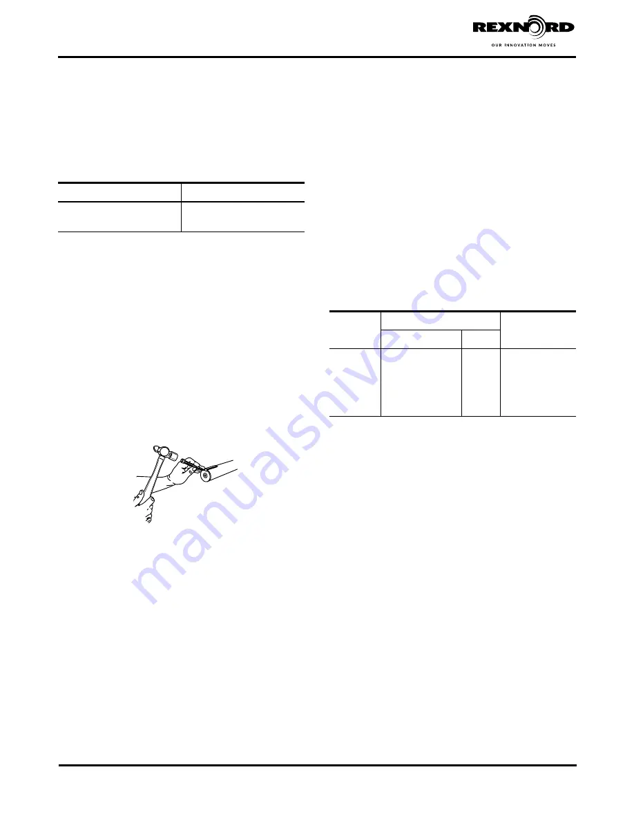
 

THICK WALL BUSHING

 (with separate internal and external 

keyways) — Insert driven shaft key into driven shaft keyway. 
If driven shaft has an open-ended keyway, stake keyway as 
illustrated in Figure 5 to prevent axial dislocation of shaft key 
under operating conditions. Slide bushing assembly onto 
driven shaft (bushing may have to be pried open slightly). 
Rotate shaft so that external keyway in bushing is at the 12 
o’clock position. Insert drive key furnished with bushing into 
bushing keyway. Proceed to Step 3.

Figure 5

3.  Using a sling, safely lift gear drive so that hollow output shaft 

is in the horizontal position. Rotate hollow shaft so that keyway 
is aligned with driven shaft/bushing key. Position and slide 
drive onto driven shaft taking care that driven shaft key seats 
into hollow shaft keyway. DO NOT hammer or use excessive 
force.

4.  Thread bushing nut onto hollow shaft one to two turns. Note: 

The bushing nut threads have been coated with an anti-seize 
compound at the Factory. This compound should not be 
removed. Before re-installing a previously used nut, recoat 
the nut threads (only) with an anti-seize compound. KEEP 
TAPERED SURFACE OF BUSHING AND HOLLOW SHAFT 
BORE FREE FROM ALL ANTI-SEIZE OR LUBRICATING 
COMPOUNDS.

5.  Tighten nut as instructed in one of the following methods.
 

PREFERRED METHOD

 — Using a spanner (Table 4) chain 

or pipe wrench, tighten bushing nut to the torque value 
specified in Table 4. Note: For applications where external 

vibratory or transient loads may act on drive and cause 
setscrews to become loose, apply Loctite 243 or equivalent to 
threads of setscrew. Tighten setscrew on bushing nut.


ALTERNATE METHOD

 — (Use this method when torque 

cannot be measured.) Using a spanner (Table 4), chain or 
pipe wrench, tighten bushing nut just until drive can no longer 
be moved by hand axially on the driven shaft. Loosen nut 
ONLY until it can be turned by hand but do not unseat the 
taper. Retighten nut hand tight. Mark a spot on top of driven 
shaft. Mark a spot on bushing nut 180° from the driven shaft 
mark (90° CCW for Sizes 04UJ & 06UJ). Using a spanner 
wrench, tighten nut CW one half turn until the two marks are 
aligned (one quarter turn for Sizes 04UJ & 06UJ). Note: For 
applications where external vibratory or transient loads may 
act on drive and cause setscrew to become loose, apply 
Loctite 243 or equivalent to threads of setscrew. Tighten 
setscrew on bushing nut.

Table 4 —  Spanner Wrench Type & Spanner Nut 

Tightening Torque

DRIVE SIZE

Adjustable Hook Spanner Wrench

Spanner Nut 

Tightening Torque 

lb-ft (Nm)

Armstrong Tools

Williams

302, 304

34-307 (2.00" - 4.75")

474

83 (113)

306

34-307 (2.00" - 4.75")

474

83 (113)

307

34-307 (2.00" - 4.75")

474

167 (226)

308

34-310 (4.50" - 6.25")

474A

167 (226)

309

34-310 (4.50" - 6.25")

474A

250 (339)

310

34-310 (4.50" - 6.25")

474A

250 (339)

312

34-313 (6.12" - 8.75")

474B

250 (339)

Removal
WARNING: 

Drive must be supported during removal process. 

Use a sling around the gear drive and take up slack before 
proceeding.

1.  Loosen setscrew on bushing nut located at output end of  

hollow shaft.

2.  Use a spanner (Table 4) pipe or chain wrench to loosen 

bushing nut. Initially, bushing nut will freely rotate counter 
clockwise approximately 180° as the nut moves from 
the locked position to the removal position. At this point 
anticipate resistance which indicates unseating of the 
bushing. Continue to turn bushing nut until it is free from the 
hollow shaft.

3.  Prepare drive for lifting by disconnecting torque arm at drive 

end. Slide drive from bushing. Note: Bushing can be left in 
place or removed, as required. If bushing will not slide off of  
shaft, insert a small pry bar into split of bushing and pry split 
open slightly to loosen bushing and remove from shaft.

Содержание Falk Ultramite UJ 302

Страница 1: ... defined and accepted in writing by Company as a condition of operation II failure to provide suitable installation environment III use for purposes other than those for which designed or other abuse or misuse IV unauthorized attachments modifications or disassembly or V mishandling during shipping General Information The following instructions apply to standard Falk Type UJ drives shown above If ...

Страница 2: ...ic housing high speed motor adapter and electric motor use Loctite 7070 Super Clean or equivalent Check for and remove any burrs from mating surfaces 4 If unit size is 308UJ or larger fill basic housing with lube type as specified in Table 13 Page 11 to the oil level plug Refer to Table 11 Page 10 for the approximate quantities of oil by the drive mounting shaft 5 Apply anti fretting compound Dow ...

Страница 3: ... backing bolt nut and flat washer required Table 2 Removal Backing Bolt Data Solid Shaft DRIVE SIZE Removal Bolt Size Minimum Length Inches Maximum Tightening Torque lb ft Nm Backing Bolt Size Maximum Length Inches 302 375 16 UNC x 1 00 37 50 375 16 UNC x 1 25 304 375 16 UNC x 1 00 37 50 375 16 UNC x 1 25 306 625 11 UNC x 1 50 183 248 625 11 UNC x 1 75 307 750 10 UNC x 1 75 330 448 750 10 UNC x 2 ...

Страница 4: ...TI SEIZE OR LUBRICATING COMPOUNDS 5 Tighten nut as instructed in one of the following methods PREFERRED METHOD Using a spanner Table 4 chain or pipe wrench tighten bushing nut to the torque value specified in Table 4 Note For applications where external vibratory or transient loads may act on drive and cause setscrews to become loose apply Loctite 243 or equivalent to threads of setscrew Tighten s...

Страница 5: ...orrosive environments consideration should be given to use of an anti seize compound on rod end threads ROD CLEVIS HARDWARE ROD CLEVIS FASTENER GEAR DRIVE HOUSING ROD CLEVIS TURN BUCKLE JAM NUTS ROD ENDS ANCHOR HARDWARE TORQUE ARM ANCHOR Figure 7 2 Thread jam nuts on rod ends far enough to allow for assembly of the turnbuckle Install rod ends into turnbuckle so that length of threads exposed in tu...

Страница 6: ...essary to heat the rod clevis using a torch to loosen rod clevis fastener 3 Remove rod clevis from torque arm loosen jam nuts and remove rod ends from turnbuckle SCREW CONVEYOR INSTALLATION AND REMOVAL INSTRUCTIONS Installation 1 Separate contents from drive shaft kit Install thrust plate and retaining ring in hollow shaft as illustrated in Figure 9 For sizes 302UJ and 304UJ drives with either 2 4...

Страница 7: ...uctions DRIVE SHAFT KEY RETAINING RING THRUST PLATE FASTENER THRUST PLATE HOLLOW SHAFT SEAL HOUSING WINDOWS SEAL HOUSING TROUGH END FASTENERS DRIVE SHAFT SEAL HOUSING FASTENERS WASTE PACKING Figure 11 Table 7 Seal Housing Trough End Fastener Data Non Lubricated Fasteners DRIVE SIZE Seal Housing Fasteners Trough End Fasteners Size Torque lb ft Nm 1 500 Dia Drive Shaft 2 000 2 437 Dia Drive Shafts 3...

Страница 8: ...king Seal or b Lip Seal Proceed as follows for removal of drive shaft from seal housing a Waste Packing Seal Figure 11 Page 7 Remove key from drive shaft keyway Remove waste packing material and remove seal housing toward tapered end of drive shaft b Lip Seal Figure 10 Page 6 Remove key from drive shaft keyway Remove any burrs from tapered end of shaft and wrap entire length with masking tape or a...

Страница 9: ...ng Rexnord specifications refer to appropriate coupling service manual GAP AND ANGULAR ALIGNMENT If possible after mounting coupling hubs position the driving and driven equipment so that the distance between shaft ends is equal to the coupling gap Align the shafts by placing a spacer block equal in thickness to required gap between hub faces as shown and also at 90 intervals around the hub Check ...

Страница 10: ...s WARNING SYNTHETIC LUBRICANTS IN FOOD PROCESSING INDUSTRY Synthetic lubricants may contain toxic substances and should not be used in the food processing industry without the lubricant manufacturer s approval Lubricants which meet NSF H1 classification are suitable for food processing applications Oil Levels Unit sizes 308UJ and above are furnished without oil Oil levels are determined by drive m...

Страница 11: ... fatty and EP additives To prevent damage to the drive through lubricant breakdown the oil should be changed at the intervals shown in Table 12 Oil Change Intervals Intervals shown are for oil temperatures when the drive has attained normal running temperature when operating under load These intervals are based on normal running Where conditions are particularly severe it may be necessary to chang...

Страница 12: ...n will not remove all grease and cross contamination will likely occur Refer to gear drive assembly disassembly instructions Grease registered as H1 by NSF National Sanitation Foundation is suitable for food processing Table 14 Conventional NLGI 2 Grade Greases for Grease Lubricated Bearings Grease Purged Seals 18 to 93 C 0 to 200 F Manufacturer Lubricant Chevron Texaco Caltex Multifak EP 2 Citgo ...

Страница 13: ...ord Corporation All Rights Reserved OIL LEVEL OIL FILL OIL DRAIN BREATHER MOUNTING 1 MOUNTING 2 MOUNTING 3 MOUNTING 4 MOUNTING 5 MOUNTING 6 Figure 13 Oil Service Location Double and Triple NOTE 302UJ and 304UJ sizes ship fully sealed and lubricated for life and do not have oil drain plugs OIL LEVEL OIL FILL OIL DRAIN BREATHER MOUNTING 1 MOUNTING 2 MOUNTING 3 MOUNTING 4 MOUNTING 5 MOUNTING 6 Mounti...

Страница 14: ...on All Rights Reserved 414 643 2366 Outside the U S MOUNTING 1 MOUNTING 2 A MOUNTING 3 B MOUNTING 4 MOUNTING 5 MOUNTING 6 VIEW B VIEW A Figure 14 Oil Service Location Quadruple and Quintuple OIL LEVEL OIL FILL OIL DRAIN BREATHER MOUNTING 1 MOUNTING 2 MOUNTING 3 MOUNTING 4 MOUNTING 5 MOUNTING 6 NOTE 302UJ and 304UJ sizes ship fully sealed and lubricated for life and do not have oil drain plugs ...

Страница 15: ...ive Gear Drives Each gear drive is protected with rust preventive that will protect parts against rust for a period of 6 months in an indoor dry shelter If a gear drive is to be stored or is inactive after installation beyond the above periods drain oil from housing and spray all internal parts with a rust preventive oil that is soluble in lubricating oil or add Motorstor vapor phase rust inhibito...

Отзывы: