


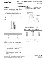


Motor Mount Installation
2.
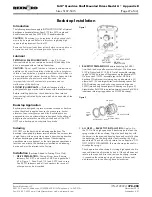
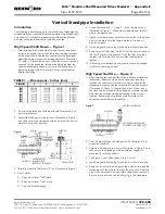
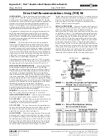
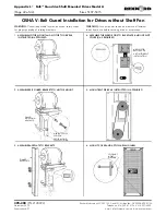
ATTACH MOTOR MOUNT TO DRIVE —
To determine the
number of housing flange fasteners to be removed for a given
shaft center and drive size, refer to Table 2. Remove and
discard appropriate number of housing flange fasteners, and
replace them with the longer support leg fasteners provided.
Attach support legs to the input side of drive with the hex nuts
on output side of drive. Tighten support leg and base plate
support fasteners to torque values specified in Table 1.
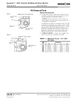
3.
MOUNT MOTOR —
Position motor on motor base
plate so that all mounting holes are in alignment. Install
and tighten motor fasteners.
4.
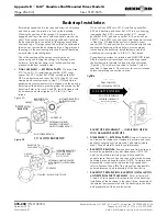
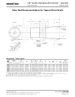
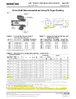
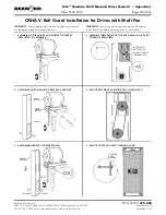
SPROCKET, PULLEY OR SHEAVE CONNECTION —
Mount power take-offs as close to drive and motor housing
as possible to avoid undue bearing load and shaft
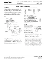
deflection. Align the high speed shaft of drive square and
parallel with motor shaft by placing a straightedge across
the face of the sprockets or sheaves as illustrated in Figure
4. Check horizontal shaft alignment by placing one leg of
a square against the face of the sheave or sprocket with
the spirit level on the horizontal leg of the square.
Adjustment of the belt or chain is accomplished by turning
adjusting screws evenly. DO NOT over tighten belts or
chains. Over tightening belts or chains reduces belt/chain
and bearing life. When the required tension is reached,
tighten adjusting screw jam nuts to torques listed in Table 1.
Adjust chain tension to manufacturer’s specifications. Adjust
belts as follows:
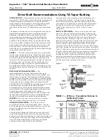
The ideal belt tension is the lowest tension at which the belt
will not slip under peak load conditions. Check belt tension
frequently during the first 24 to 48 hours of run-in operation.
Keep belts free from foreign material which may cause
slippage. Inspect the V-belt drive periodically; re-tighten belts
if they are slipping.
Rexnord Industries, LLC 3001 W. Canal St., Milwaukee, WI 53208-4200 USA
378-200
(PN-2128394)
Telephone: 414-342-3131 Fax: 414-937-4359
November 2010
e-mail: [email protected] web: www.rexnord.com
Supersedes 6-07
S
SHORT
CENTERS
M
M EDIUM
CENTERS
L
LONG
CENTERS
TABLE 2 — Support Leg Fastener Quantity
(Each Side)
Shaft
Centers
DRIVE SIZE
5107
5115
5203
5207
5215
5307
5315
Short
NA
NA
4
4
4
6
Medium
3
3
3
3
3
5
Long
2
2
2
2
2
4
Figure 3
RIGHT
WRONG
GEAR DRIVE WALL
LEVEL
SQUARE AND
PARALLEL
Figure 4
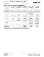
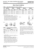
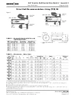
TABLE 1 — Motor Mount Fasteners & Torques
H
lb-ft (Nm)
DRIVE
SIZE
Support Leg to
Baseplate Support
Support Leg
to Housing
Adapter Plate to
Baseplate Support
Adjusting Screws
(W/O Adapter)
Adjusting Screws
(With Adapter)
Fastener Size
Tightening
Torque
Fastener Size
Tightening
Torque
Fastener Size
Tightening
Torque
Fastener Size
Tightening
Torque
Fastener Size
Tightening
Torque
5107
.375-16UNC x 1.00
28 (38)
.312-18UNC x 1.50
20 (26)
. . .
. . .
.625-11UNC x 5.00
60 (81)
. . .
. . .
5115
.375-16UNC x 1.00
28 (38)
.312-18UNC x 1.50
20 (26)
.625-11UNC x 1.00
60 (81)
.625-11UNC x 5.00
60 (81)
.750-10UNC x 6.00
108 (146)_
5203
.500-13UNC x 1.25
69 (94)
.375-16UNC x 2.00
28 (38)
.625-11UNC x 1.00
60 (81)
.625-11UNC x 5.00
60 (81)
1.000-8UNC x 6.00
180 (244)
5207
.500-13UNC x 1.25
69 (94)
.500-13UNC x 2.25
69 (94)
.625-11UNC x 1.00
60 (81)
.625-11UNC x 5.00
60 (81)
1.250-7UNC x 7.00
362 (491)
5215
.625-11UNC x 1.50 137 (186)
.500-13UNC x 2.25
69 (94)
.625-11UNC x 1.00
60 (81)
.625-11UNC x 5.00
60 (81)
1.250-7UNC x 7.00
362 (491)
5307
.750-10UNC x 1.75 245 (332)
.500-13UNC x 2.50
69 (94)
.625-11UNC x 1.00
60 (81)
.625-11UNC x 5.00
60 (81)
1.250-7UNC x 7.00
362 (491)
5315
.750-10UNC x 1.75 245 (332)
.500-13UNC x 2.50
69 (94)
.625-11UNC x 1.00
60 (81)
.625-11UNC x 5.00
60 (81)
1.250-7UNC x 7.00
362 (491)
H
All fasteners are Grade 5.
Appendix D
•
Falk™ Quadrive Shaft Mounted Drives Model A
(Page 32 of 44)
Sizes 5107-5315


