


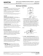
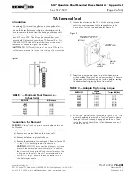
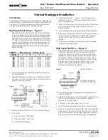

(5) Low Speed Shaft Axial Float Measurement — Ref.
#4A Assembly – For drives equipped with TA Taper
bushing, carefully thread bushing nut onto hollow low
speed shaft threads. Rotate shaft to seat cone
assemblies in bearing cups. Set up a dial indicator on
output housing as illustrated in Figure 24. Indicator tip
must rest on low speed shaft and not on nut surface.
Rotate and oscillate shaft with axial force applied in
both directions to obtain axial float measurement.
For drives without the TA Taper bushing, insert hollow
shaft thrust plate and secure with retaining ring as
illustrated in Section
I
, Figure 5. Thread a bolt into
the thrust plate. Set up a dial indicator on output
housing, as illustrated in Figure 24, with the indicator
tip on end of hollow shaft. Rotate and oscillate shaft
with axial force applied in both directions to obtain
axial float measurement. (Upward force can be
applied by applying upward force on head of thrust
plate bolt.)
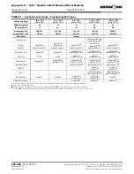
Refer to Table 15 and note the preload specified for
bearings 4A1 and 4A2. Add to upper and lower
limits shown, the axial float measured. This will
indicate thickness of metal shim(s), Ref. #31, to be
added behind input housing bearing cup to obtain
the specified preload. Table 16 provides shim
thickness for each shim pack to assist in obtaining
the desired results.
For example, from Table 15 the desired bearing preload
for the Size 5203 low speed shaft bearings, Ref. #4A1 &
4A2, is .002” to .004” (0,05 mm to 0,10 mm) tight. If the
measured axial float is .039” (0,99mm) then addition of
metal shims with a total thickness between .041” to .043”
(1,04 mm to 1,09 mm) behind the low speed input
housing bearing cup will produce the desired preload.
(6) With drive resting on input housing cover, Ref. #10,
tap the dowel pins out of the housing, remove flange
fasteners and set output housing aside. Remove low
speed shaft assembly and bearing cups. Install metal
shim(s), as determined in Step 6b5, behind bearing
cup in input housing.
Reinstall dowels, shims and output housing cover &
torque housing flange fasteners, Ref. #25, to value
in Table 14. Proceed to Step 7.
(7) Lower low speed, Ref. #4A, high speed, Ref. #1A (or
3A), and intermediate, Ref. #2A shaft assemblies into
input housing. Reinstall dowels and output housing
and torque flange fasteners to value listed in Table
14. Recheck low speed shaft with dial indicator to
ensure that no float is present. Measure intermediate
and high speed shaft float with a dial indicator in
accordance with methods described below.
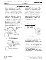
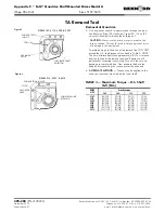
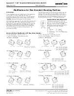
(8)
INTERMEDIATE SHAFT AXIAL FLOAT
MEASUREMENT —
Ref. #2A Assembly – Figure 25.
Remove pipe plug from output housing cover. Install
a .375-16 x 2” size bolt through hole in housing and
turn by hand until snug. Set up a dial indicator on output
housing with the indicator tip on bolt head as illustrated
in Figure 26. While turning bolt in a clockwise direction,
lift upward to measure axial float. Subtract from this
reading the axial float for the Ref. #2A shaft assembly
shown in Table 15. This indicates the thickness of metal
shim(s), Ref. #22 to be added behind the input housing
bearing cup to obtain the specified axial float.
For example, from Table 15 the desired axial float
for the Size 5307 intermediate shaft assembly, Ref.
#2A, is .001” to .003” (0,03 mm to 0,08 mm). If
the measured axial float is .039” (0,99 mm) then
addition of metal shims with a total thickness
between .036” to .038” (0,91 mm to 0,96 mm)
behind the intermediate speed input housing bearing
cup will produce the desired axial float.
Rexnord Industries, LLC 3001 W. Canal St., Milwaukee, WI 53208-4200 USA
378-200
(PN-2128394)
Telephone: 414-342-3131 Fax: 414-937-4359
November 2010
e-mail: [email protected] web: www.rexnord.com
Supersedes 6-07
Owners Manual
•
Falk™ Quadrive Shaft Mounted Drives Model A
(Page 20 of 44)
Sizes 5107-5315
DIAL INDICATOR
WITH STAND
DIAL INDICATOR TIP MUST
REST ON QUILL SHAFT AND
NOT ON NUT SURFACE
PRY BAR
BUSHING NUT
THREADED ON
QUILL SHAFT
0
4
4
3
3
2
2
1
1
5
Figure 24
TABLE 15 — Preload & Axial Float Settings
DRIVE
SIZE
Ref. #4A1 & 4A2
Bearing Preload
Inches (mm)
Ref. #2A3 Assembly
Intermediate Shaft
Axial Float
Inches (mm)
Ref. #1A3 or 3A3
Assembly
High Speed Shaft
Axial Float
Inches (mm)
5107
0.001-0.004 (0,00-0,10)
.001-.003 (0,03-0,08)
.001-.003 (0,03-0,08)
5115
0.111-0.004 (0,00-0,10)
.001-.003 (0,03-0,08)
.001-.003 (0,03-0,08)
5203
0.001-0.004 (0,00-0,10)
.001-.003 (0,03-0,08)
.001-.003 (0,03-0,08)
5207
0.001-0.004 (0,00-0,10)
.001-.003 (0,03-0,08)
.001-.003 (0,03-0,08)
5215
0.001-0.004 (0,00-0,10)
.001-.003 (0,03-0,08)
.001-.003 (0,03-0,08)
5307
0.001-0.004 (0,00-0,10)
.001-.003 (0,03-0,08)
.001-.003 (0,03-0,08)
5315
.0.001-0.004 (0,00-0,10)
.001-.003 (0,03-0,08)
.001-.003 (0,03-0,08)
TURN AND MOVE
BOLT TO CHECK
FLOAT
Figure 25


