background image

en

41

Installation

Indications,

 functions and options

Messages

Commissioning

Operation and function

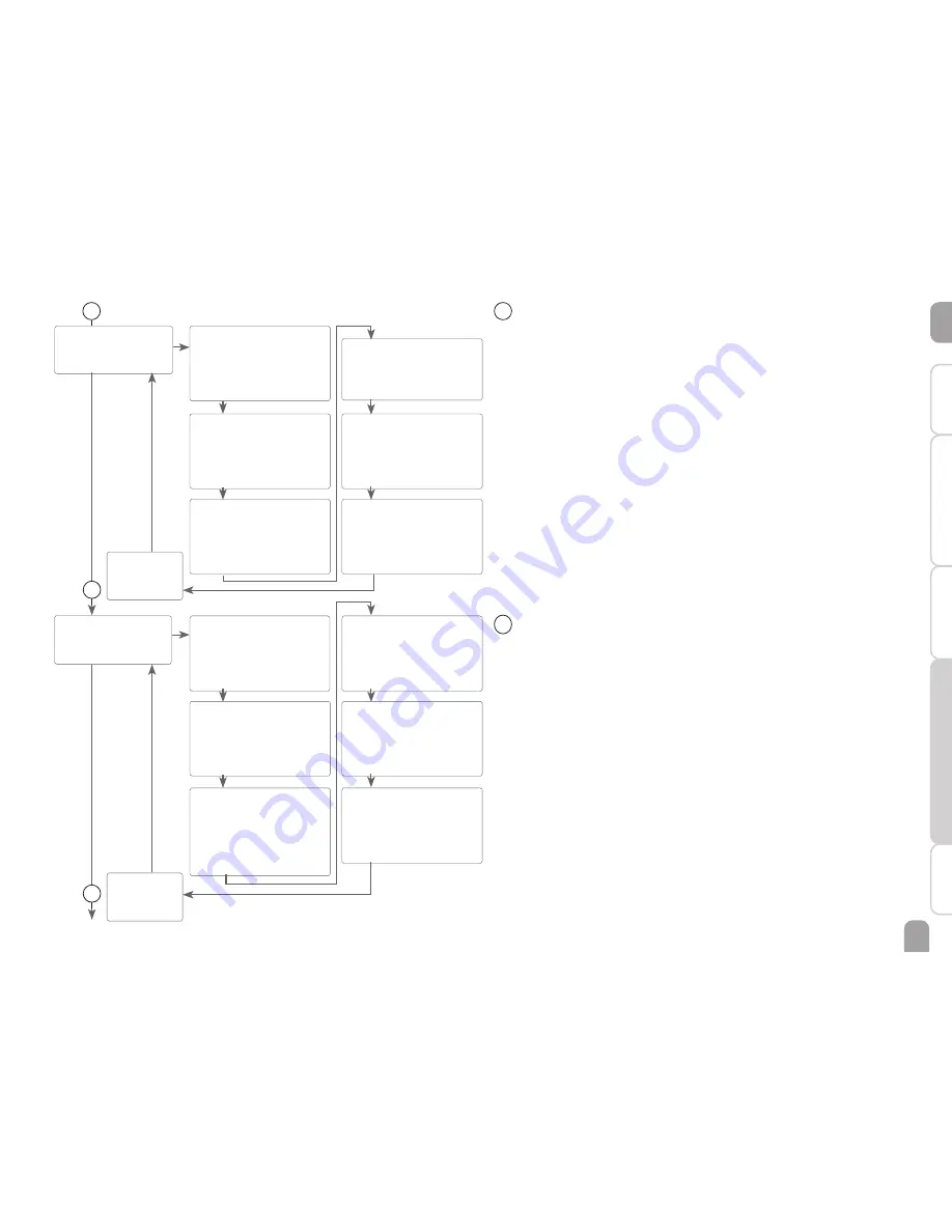
HEATX 10

PUSH

DTHXO 
Switch-on temperature diff. 
Adjustment range: 
1.0 … 50.0 K 
Factory setting: 6.0 K

DTHXF
Switch-on temperature diff. 
Adjustment range: 
0.5 … 49.5 K
Factory setting: 4.0 K

DTHXS
Set temperature diff. 
Adjustment range: 
1.5 … 50.0 K 
Factory setting: 10.0 K

MXHXO
Maximum limitation
Adjustment range: 
0.5 … 95.0 °C
Factory setting: 60.0 °C

RISHX
Rise 
Adjustment  range:  1 … 20 K 
Factory setting: 2 K

MNHXO
Minimum limitation
Adjustment range: 
0.5 … 89.5 °C
Factory setting: 60.0 °C

10  Heat exchange function

The heat exchange function can be used for transferring heat from a heat source 
to a heat sink.
The relay (system-dependent) is energised when all switch-on conditions are ful-
filled:
•  the temperature difference between the sensors heat source and heat sink has 

exceeded the switch-on temperature difference.

•  the temperature at the heat source sensor has exceeded the minimum temperature
•  the temperature at the heat sink sensor has fallen below the maximum temperature
When the Set temperature difference is exceeded, pump speed control starts. For 
every increase or decrease by the rise value, the pump speed will be adjusted by 10 %.

10

11

BACK

PUSH

BACK

PUSH

AH  

11

PUSH

AH O 
Thermostat switch-on temp.
Adjustment range: 
0.5 … 95.0 °C  in  steps  of  0.5 °C 
Factory setting: 40.0 °C

AH F 
Thermostat switch-off temp.
Adjustment range: 
0.5 … 94.5 °C  in  steps  of  0.5 °C 
Factory setting: 45.0 °C

t1O
Switch-on time 1
Adjustment range: 
00:00 … 23:45
Factory setting: 06:00 
in steps of 15 min

t2 (3) O
Switch-on time 2 (3)
Adjustment range: 
00:00 … 23:45
Factory setting: 00:00

t1F
Switch-off time 1
Adjustment range: 
00:00 … 23:45
Factory setting: 22:00

t2 (3) F
Switch-off time 2 (3)
Adjustment range: 
00:00 … 23:45
Factory setting: 00:00

12

11  Afterheating / Thermostat  function

The thermostat function works independently from the solar operation and can e. 
g. be used for using surplus energy or for afterheating.
•  AH O < AH F thermostat function for afterheating
•  AH O > AH F thermostat function for using surplus energy
In order to block the thermostat function for a certain period, there are 3 time 
frames t1 … t3. The switch-on and switch-off times can be adjusted in steps of 15 
min. If the switch-on and the switch-off times are identical, the time frame is inactive.
If the thermostat function is supposed to run from 06:00 a.m. and 09:00 a.m. only, 
adjust t1 O to 06:00 a.m. and t1 F to 09:00 a.m. 
The first time frame is factory set from 06:00 to 22:00. 
If all time frames are set to 00:00, the thermostat function is solely temperature 
dependent.

Содержание DeltaSol SLL

Страница 1: ...t Please keep this manual safe DeltaSol SLL www resol com Manual en Solar controller Manual for the specialised craftsman Installation Operation Functions and options Troubleshooting 11205585 11205585 The Internet portal for easy and secure access to your system data www vbus net beginning with firmware version 1 05 ...

Страница 2: ...lds Subject to technical change Errors excepted Target group These instructions are exclusively addressed to authorised skilled personnel Only qualified electricians should carry out electrical works Initial installation must be effected by the system owner or qualified personnel named by the system owner Description of symbols WARNING Warnings are indicated with a warning triangle Î Î They contai...

Страница 3: ... 2 2 Electrical connection 5 2 3 Data communication Bus 6 2 4 System overview 7 2 5 Systems 8 3 Operation and function 18 3 1 Buttons and adjustment dial 18 3 2 Microbutton for manual mode and holiday mode 18 3 3 Control lamp 19 3 4 Menu structure 19 3 5 Selecting menu points and adjusting values 19 3 6 resetting balance values 20 4 System Monitoring Display 20 4 1 System screen 21 4 2 Further ind...

Страница 4: ...Energy efficiency contribution 1 Mode of operation Type 1 B C Y Rated impulse voltage 2 5 kV Data interface RESOLVBus VBus current supply 60 mA Functions operating hours counter tube collector function thermostat function pump speed control heat quantity measurement adjustable system parameters and optional functions menu driven balance and diagnostics function function control according toVDI 216...

Страница 5: ...n see chap 2 2 Î Î Put the cover on the housing Î Î Attach with the fastening screw 2 2 Electrical connection WARNING Electric shock Upon opening the housing live parts are exposed Î Î Always disconnect the controller from power supply before opening the housing ATTENTION ESD damage Electrostatic discharge can lead to damage to electronic components Î Î Take care to discharge properly before touch...

Страница 6: ... Protective conductor Note The connection depends on the system layout selected see page 7 Note For more details about the initial commissioning procedure see page 23 2 3 Data communication Bus The controller is equipped with the RESOL VBus for data transfer and energy supply to external modules The connection is to be carried out at the two termi nals marked VBus any polarity One or more RESOLVBu...

Страница 7: ...ore and return preheating page 16 2 Solar system with 2 stores and heat exchange page 9 6 Solar system with 2 stores and pump control page 13 10 Solar system with 1 store and heat dump page 17 3 Solar system with 1 store and afterheating page 10 7 Solar system with east west collectors page 14 4 Solar system with 1 store and 3 port valve for store loading in layers page 11 8 Solar system with 1 st...

Страница 8: ...sted switch on temperature difference the pump R1 will be switched on and the store will be loaded until the switch off temperature difference or the maximum store temperature is reached System 1 system screen Temperature sensors S1 Temperature collector 1 GND S2 Temperature store base 2 GND S3 Free 3 GND S4 Free 4 GND Relay R1 Solar pump R1 N PE R2 Free R2 N PE R4 Free R4 R4 S2 R1 S1 VBus VBus V4...

Страница 9: ...erature difference or the maximum store temperature is reached Heat exchange control to an existent store via an additional pump R2 can be carried out with another temperature differential function S3 heat source S4 heat sink System 2 system screen Temperature sensors S1 Temperature collector 1 GND S2 Temperature store base 2 GND S3 Temperature heat exchange source 3 GND S4 Temperature heat exchan...

Страница 10: ...ature is reached Afterheating R2 and R4 can be carried out with a thermostat function S3 If the value at S3 reaches the switch on temperature for the afterheating the relay is switched on If the value exceeds the switch off temperature for the afterheating the relay is switched off again System 3 system screen R1 S2 S1 R2 R4 N N N N 10 11 3 3 2 2 2 3 2 S3 VBus VBus V40 S4 S3 GND Sensors Relais S2 ...

Страница 11: ...ated and the corresponding store zone will be loaded up to the adjusted store maximum or set temperature respectively via the valve R2 The priority logic effects prior loading of the upper zone of the store System 4 system screen Temperature sensors S1 Temperature collector 1 GND S2 Temperature store base 2 GND S3 Temperature store top 3 GND S4 Free 4 GND Relay R1 Solar pump R1 N PE R2 Valve Solar...

Страница 12: ...e activated and the corresponding store will be loaded up to the adjusted store maximum or set temperature respectively via the valve R2 The priority logic effects prior loading of store 1 System 5 system screen Temperature sensors S1 Temperature collector 1 GND S2 Temperature store base 2 GND S3 Free 3 GND S4 Temperature store 2 base 4 GND Relay R1 Solar pump R1 N PE R2 Valve Solar R2 N PE R4 Fre...

Страница 13: ... will be activat ed and the corresponding store will be loaded up to the adjusted store maximum or set temperature respectively at most The priority logic effects prior loading of store 1 System 6 system screen R2 R1 S4 S2 S1 N N N N 10 11 2 3 3 2 2 3 VBus VBus V40 S4 S3 GND Sensors Relais S2 S1 N R2 R1 L R4 R4 R2 R1 L 1 2 3 4 5 6 7 8 9 PWM A PWM B Temperature sensors S1 Temperature collector 1 GN...

Страница 14: ...ence the corresponding pump R1 and or R2 will be switched on thus loading the store until either the switch off temperature difference or the store maximum temperature is reached System 7 system screen R2 R1 S2 S1 S4 N N N N 10 11 3 3 2 2 3 2 VBus VBus V40 S4 S3 GND Sensors Relais S2 S1 N R2 R1 L R4 R4 R2 R1 L 1 2 3 4 5 6 7 8 9 PWM A PWM B Temperature sensors S1 Temperature collector 1 GND S2 Temp...

Страница 15: ... off temperature difference or the maximum store temperature is reached With another temperature differential function S4 heat source S3 heat sink after heating of the store with a solid fuel boiler can be carried out via another pump R2 System 8 system screen N N N N 10 11 3 3 2 2 2 3 2 R2 R1 S4 S3 S2 S1 VBus VBus V40 S4 S3 GND Sensors Relais S2 S1 N R2 R1 L R4 R4 R2 R1 L 1 2 3 4 5 6 7 8 9 PWM A ...

Страница 16: ...fference or the maximum store temperature is reached With another temperature differential function S3 heat source S4 heat sink return preheating heating circuit backup is possible via another valve R2 System 9 system screen Temperature sensors S1 Temperature collector 1 GND S2 Temperature store base 2 GND S3 Temperature store return preheating 3 GND S4 Temperature heating return 4 GND Relay R1 So...

Страница 17: ... the collector maximum temperature CMAX is reached the solar pump will be energised by R1 and the 3 port valve by R2 in order to divert excess heat to a heat sink For safety reasons excess heat dump will only take place as long as the store temperature is below the non adjustable shutdown temperature of 95 C 200 F System 10 system screen Temperature sensors S1 Temperature collector 1 GND S2 Temper...

Страница 18: ...on The microbutton is used for activating the holiday function see page 43 If the microbutton is pressed and held down for approx 3 s the adjustment channel DAYS appears allowing to enter the number of days for an absence If the parameter is set to a value higher than 0 the function becomes active using the adjustments that have previously been made in the H DAY menu The days will be counted backw...

Страница 19: ...consists of sub menus and adjustment channels In order to activate or deactivate a function it must be selected in the menu level The display changes to the adjustment menu in which all adjustments required can be carried out Note Some of the menu items depend on the selected system and the adjusted options Therefore they are only displayed if they are available Note The abstract from the menu str...

Страница 20: ...ct the desired adjustment channel by turning the Lightwheel Î Confirm your selection with the right button Ⓢ starts flashing ad justment mode Î Adjust the value by turning the Lightwheel Î Confirm your selection with the right button Ⓢ permanently appears the adjustment has been saved BACK PUSH appears as the last display Î In order to get back to the menu selection press the right button If no bu...

Страница 21: ...t indication If the controller detects a malfunction the control LED flashes red and the symbols of the warning triangle and the wrench are additionally displayed Short text and ticker Functions options measurement and balance values as well as messages are in dicated as both short text and ticker After the short text has been displayed the corresponding long text will be indicated as a ticker fro...

Страница 22: ... sensor 3 S4 Temperature sensor 4 n1 Speed relay 1 n2 Speed relay 2 L h Flow rate sensorV40 TFHQM Heat quantity measurement flow temperature TRHQM Heat quantity measurement return temperature kWh Heat quantity in kWh MWh Heat quantity in MWh BLPR Blocking protection relay 1 BLPR2 Blocking protection relay 2 INIT Initialisation drainback FLLT Filling time drainback STAB Stabilisation drainback TDIS...

Страница 23: ...the system Commissioning menu The commissioning menu consists of the channels described in the following In order to make an adjustment press the right button Ⓢ starts flashing and the adjustment can be made Confirm the adjustment with the right button Turn the Lightwheel the next channel will appear on the screen Adjustment mode flashing Operation changing a value flashing confirming a value not ...

Страница 24: ...ximum store temperature Î Adjust the maximum store temperature In 2 store systems the adjustment has to be carried out for S2MAX aswell see page 33 8 Loading store 1 Î Switch on or off the loading store 1 option see page 33 Note Loading store 1 is only available if a 2 store system or store loading in layers has been previously selected in the sub channel SYS 10 Relay control type Î Select the rel...

Страница 25: ...he sub channel REL REL2 Commissioning Î Complete the commissioning menu by pressing the right button The controller is then ready for operation and nor mally the factory settings will give close to optimum operation Note The adjustments carried out during commis sioning can be changed anytime in the cor responding adjustment channel Additional functions and options can also be activated or deactiv...

Страница 26: ... and parameters can be downloaded at www resol com 8 1 Status level Display of blocking protection time BLPR 2 Blocking protection active Display of drainback time periods INIT Initialisation active Indicates the time adjusted in tDTO running backwards FLLT Filling time active Indicates the time adjusted in tFLL running backwards STAB Stabilisation Indicates the time adjusted in tSTB running backw...

Страница 27: ...ent temperature at the corresponding additional sensor without control function S3 Temperature sensor 3 S4 Temperature sensor 4 Note In systems with return preheating S3 is used as the heat source sen sor TSTR Display of further temperatures TSFB etc Further measured temperatures Indication range 40 260 C Indicates the current temperature at the corresponding sensor The display of these temperatur...

Страница 28: ...results from the sum of both values The accumulated heat quantity can be set back to zero see page 20 Indication of thermal disinfection TDIS Disinfection temperature Indication range 40 260 C If the thermal disinfection option OTDIS is activated and the disinfection period is in progress the disinfection temperature measured at the reference sensor is displayed in this channel CDIS Countdown moni...

Страница 29: ... range 0 00 23 59 hh mm If the thermal disinfection option OTDIS is activated and the disinfection period is in progress the remaining time of the heating period is displayed in hours and minutes in this channel counting backwards Display of time Time Indicates the current clock time Display of date DATE Indicates the current date ...

Страница 30: ...DAY FUNCTION SENS 20 SENSORS COL 5 COOL AH 11 AFTERHEATING OTDIS 17 THERMAL DISINFECTION VDI 23 FUNCTION CONTROL VDI 2169 LOAD 3 LOADING STORE SFB 9 SOLID FUEL BOILER MAN 15 MANUAL MODE DATE 21 DATE COL 2 6 COLLECTOR 2 RPH 12 RETURN PREHEATING OPARR 18 PARALLEL RELAY CODE 24 USER CODE RESET 25 FACTORY SETTING P 31 P 36 P 42 P 46 P 31 P 39 P 43 P 47 P 32 P 40 P 44 P 48 P 32 P 41 P 44 P 48 P 34 P 41...

Страница 31: ...to zero see page 20 Operating days Display of operating days since commissioning or last reset The operating days cannot be set back to zero Minimum and maximum temperatures MAXS1 2 3 4 Maximum temperatures at S1 S4 MINS1 2 3 4 Minimum temperatures at S1 S4 Indication of the minimum and maximum temperatures at S1 S4 The temperature indication can be set back to zero see page 20 2 System Selecting ...

Страница 32: ...f the temperature difference reaches the adjusted nominal value the pump speed increases by one step 10 The response of the controller can be adapted via the parameter Rise Each time the difference increases by the adjustable rise value the pump speed increases by 10 until the maximum pump speed of 100 is reached If the temperature difference decreases by the adjustable rise value pump speed will ...

Страница 33: ...imum limitation can be selected The maximum limitation always refers to the sensor selected The switch on hysteresis is selectable Note In systems with 2 stores or store loading in layers 2 separate menus LOAD and LOAD 2 will be displayed Loading store In systems with 2 stores or store loading in layers one of the two stores or the store zone respectively can be switched off with the parameter LST...

Страница 34: ...keeps the collector rise temperature within the operating range by heating the store If the store temperature reaches 95 C the function will switch off for safety reasons When the store temperature exceeds the adjusted maximum store temperature the solar system switches off If the collector temperature increases to the adjusted maximum collector temperature the solar pump is activated until the co...

Страница 35: ...d minimum speed If the collector sensor is defective or the collector is blocked this function is sup pressed or switched off 2 collector systems In 2 collector systems the tube collector function is available for each individual collector field In 2 collector systems the tube collector function will affect the inactive collector field only The solar pump of the active collector field will remain ...

Страница 36: ... temperature off Adjustment range 39 9 C Factory setting 5 C OCFR PUSH OK OFF ON c a BACK PUSH BACK PUSH 7 Drainback option In a drainback system the heat transfer fluid will flow into a holding tank if solar loading does not take place The drainback option initiates the filling process if solar loading is about to start If the drainback option is activated the following adjust ment can be made No...

Страница 37: ...on will not be available Booster function This function is used for additionally switching on a second pump when filling the system When solar loading starts R2 is energised in parallel to R1 After the filling time has elapsed R2 switches off Note The booster function is available in system 1 only Successive loading option Successive loading means that the priority store will be loaded up to its m...

Страница 38: ...the priority store is fulfilled it will be loaded If the switch on condition of the priority store is not fulfilled loading of the second store will be continued If the priority store reaches its set temperature store se quence control will not be carried out The minimum runtime of each loading process is 3 min In systems with 2 stores or store loading in layers all stores store zones will be load...

Страница 39: ...s active is displayed flashing Note This function will only be available if the collector cooling function the heat dump function and the drainback option are not activated Store cooling When the store cooling function is activated the controller aims to cool down the store during the night in order to prepare it for solar loading on the following day If the adjusted maximum store temperature is e...

Страница 40: ...collector cooling function the heat dump function and the drainback option are deactivated 10 9 a d e f OTCL Overtemperature collector Adjustment range 40 160 C Factory setting 110 C OTPUM Pump or valve logic Selection OFF ON Factory setting OFF SFB 9 PUSH DTSFO Switch on temperature diff Adjustment range 1 0 50 0K Factory setting 6 0 K DTSFF Switch on temperature diff Adjustment range 0 5 49 5K F...

Страница 41: ...peed will be adjusted by 10 10 11 BACK PUSH BACK PUSH AH 11 PUSH AH O Thermostat switch on temp Adjustment range 0 5 95 0 C in steps of 0 5 C Factory setting 40 0 C AH F Thermostat switch off temp Adjustment range 0 5 94 5 C in steps of 0 5 C Factory setting 45 0 C t1O Switch on time 1 Adjustment range 00 00 23 45 Factory setting 06 00 in steps of 15 min t2 3 O Switch on time 2 3 Adjustment range ...

Страница 42: ... Adjustment range 20 100 Factory setting 20 13 Relay control With this parameter the relay control type can be adjusted The following types can be selected Adjustment for standard pump without speed control ONOF Pump on pump off Adjustment for standard pump with speed control PULS Burst control via semiconductor relay Adjustment for high efficiency pump HE pump PSOL PWM profile solar pump PHEA PWM...

Страница 43: ... by strong solar irradiation from the store to an external heat exchanger e g fan coil or radiator in order to prevent the collectors from overheating The store heat dump function is independent of the solar system and can be activated with the parameter OHDPS The function uses the adjustable switch on and switch off temperature differences DTO and DTF If temperature measured at sensor 3 reaches t...

Страница 44: ...or information about the control LED in the Lightwheel see page 19 MAN 15 PUSH BLPR 16 PUSH MAN1 2 Adjustment range AUTO ON OFF MIN MAX Factory setting AUTO BLPR Adjustment range ON OFF Factory setting OFF MAN4 Adjustment range AUTO ON OFF Factory setting AUTO 16 Blocking protection In order to protect the pumps against blocking after standstill the controller is equipped with a blocking protectio...

Страница 45: ...n delayed until that starting time after the monitoring period has ended If the monitoring period ends for example at 12 00 o clock and the starting time has been set to 18 00 the reference relay will be energised with a delay of 6 hours at 18 00 instead of 12 00 o clock Note If the thermal disinfection option is activated the display channels TDIS CDIS SDIS and DDIS will be displayed OTDIS 17 PUS...

Страница 46: ...outV40 flowmeter or withV40 flowmeter Note The most precise heat quantity measurement is achieved by using sensors in the flow and return pipes as well as a flowmeter In 2 collector systems heat quantity measurement can only be carried out with sensors installed in the common flow and return pipes Flow sensor V40 flowmeter Return sensor Example of flow and return sensor positions for heat quantity...

Страница 47: ...LS Heat quantity measurement withV40 flowmeter The heat quantity measurement uses the difference between the flow and return temperatures and the flow rate transmitted by the flowmeter Î Î Adjust 2 in the channel FTYPE Î Î Adjust the antifreeze type and concentration of the heat transfer fluid in the channels MEDT and MED HQM sensors The flow sensor as well as the return sensor can be selected for...

Страница 48: ...g 03 YYYY Year Adjustment range 2010 2099 Factory setting 2010 DD Day Adjustment range 01 31 Factory setting 15 21 Time and date The controller is equipped with a real time clock required e g for the thermostat function In the display the lower line indicates the day followed by the month 21 22 Language In this adjustment channel the menu language can be chosen DE German EN English FR French ES Sp...

Страница 49: ...blems in the collector air inside the pipework defective valve defective pump Night circulation This function can be used for detecting thermal circulation inside the solar circuit that leads to an unwanted cooling of the store A warning message will appear when the following condition has been detected for at least 1 min during the period be tween 11 p m and 5 a m collector temperature exceeds 40...

Страница 50: ...dered exceeded when the temperature measured at the store sensor exceeds the adjusted maximum store temperature by at least 5 K The monitoring becomes active again as soon as the store temperature falls below the adjusted maximum store temperature The channels ST1 ST2 can be used for selecting the stores to be monitored The number of exceedances is displayed in the ST 2 MX channels A possible caus...

Страница 51: ...a message is indicated in the status display A warning triangle is additionally indicated If more than one error or fault condition has occurred only the one with the highest priority will be displayed as a message in the status display Error code display Plain text display Monitoring function Cause 0001 LINE BREAK SENSOR X Sensor line break Sensor line broken 0002 SHORT CIRCUIT SENSOR X Sensor sh...

Страница 52: ...orrespond with the table C F Ω Pt500 Ω Pt1000 Ω KTY C F Ω Pt500 Ω Pt1000 Ω KTY 10 14 481 961 1499 55 131 607 1213 2502 5 23 490 980 1565 60 140 616 1232 2592 0 32 500 1000 1633 65 149 626 1252 2684 5 41 510 1019 1702 70 158 636 1271 2778 10 50 520 1039 1774 75 167 645 1290 2874 15 59 529 1058 1847 80 176 655 1309 2971 20 68 539 1078 1922 85 185 664 1328 3071 25 77 549 1097 2000 90 194 634 1347 317...

Страница 53: ...e The temperature difference between store and collector increases enormous ly during operation the collector circuit cannot dissipate the heat Collector circuit pump defective no yes Heat exchanger calcified yes Check replace it Decalcify it no Heat exchanger blocked yes no Clean it Heat exchanger too small yes Change Ton and Toff corre spondingly Switch on temperature difference Ton too large no...

Страница 54: ...e water flow sidewards or through a siphon downwards less store losses now no yes o k a Collector temperature at night is higher than the outdoor temperature no yes Controller might be defective re place it Is the pump stuck Turn the pump shaft using a screw driver now passable Pump is defective replace it yes no Does the DHW circulation run for a very long time no yes Use the circulation pump wit...

Страница 55: ...5 en 12 Accessories Temperature sensors Overvoltage protection device V40 flowmeter SD3 Smart Display GA3 Large Display AM1 Alarm Module DL3 Datalogger DL2 Datalogger VBus USB VBus LAN interface adapters ...

Страница 56: ...onnected to theVBus of the controller and issues an optical signal via the red LED if a failure has occurred The AM1 also has a relay output which can e g be connected to a building management system BMS Thus a collective error message can be issued in the case of a system failure DL3 Datalogger Be it solar thermal heating or DHW heat exchange controllers with the DL3 you can easily and convenient...

Страница 57: ...Holiday function 43 L Language 48 M Manual mode 44 Menu overview 30 Menu structure 19 Messages 51 Microbuttons 18 Minimum and maximum temperatures 31 Monitoring Display 20 Mounting 5 N Night circulation 49 O Operating days 31 P Parallel relay 45 Priority logic 33 Protection against Legionella 45 R Relay control 42 resetting balance values 20 Return preheating 42 S Solid fuel boiler 40 Speed contro...

Страница 58: ...58 en ...

Страница 59: ...59 en ...

Страница 60: ...or the completeness of the drawings and texts of this manual they only represent some examples They can only be used at your own risk No liability is assumed for incorrect incomplete or false information and or the resulting damages Note The design and the specifications can be changed without notice The illustrations may differ from the original product Imprint This mounting and operation manual ...

Отзывы: