background image

IC Live Users Manual, ICL-F & ICL-F-DUAL

19

Now, it’s time to locate (position) the steerable column. Usually it will be on the front wall (X = 0.00) on the New RH BeamWare Project dis-

play. If it will be placed at the front of the stage away from the wall, for example, move it forward by inserting its correct location. Note that

after you insert a figure in the field, you need to press Enter on your keyboard to OK the change in location. The down arrow associated with

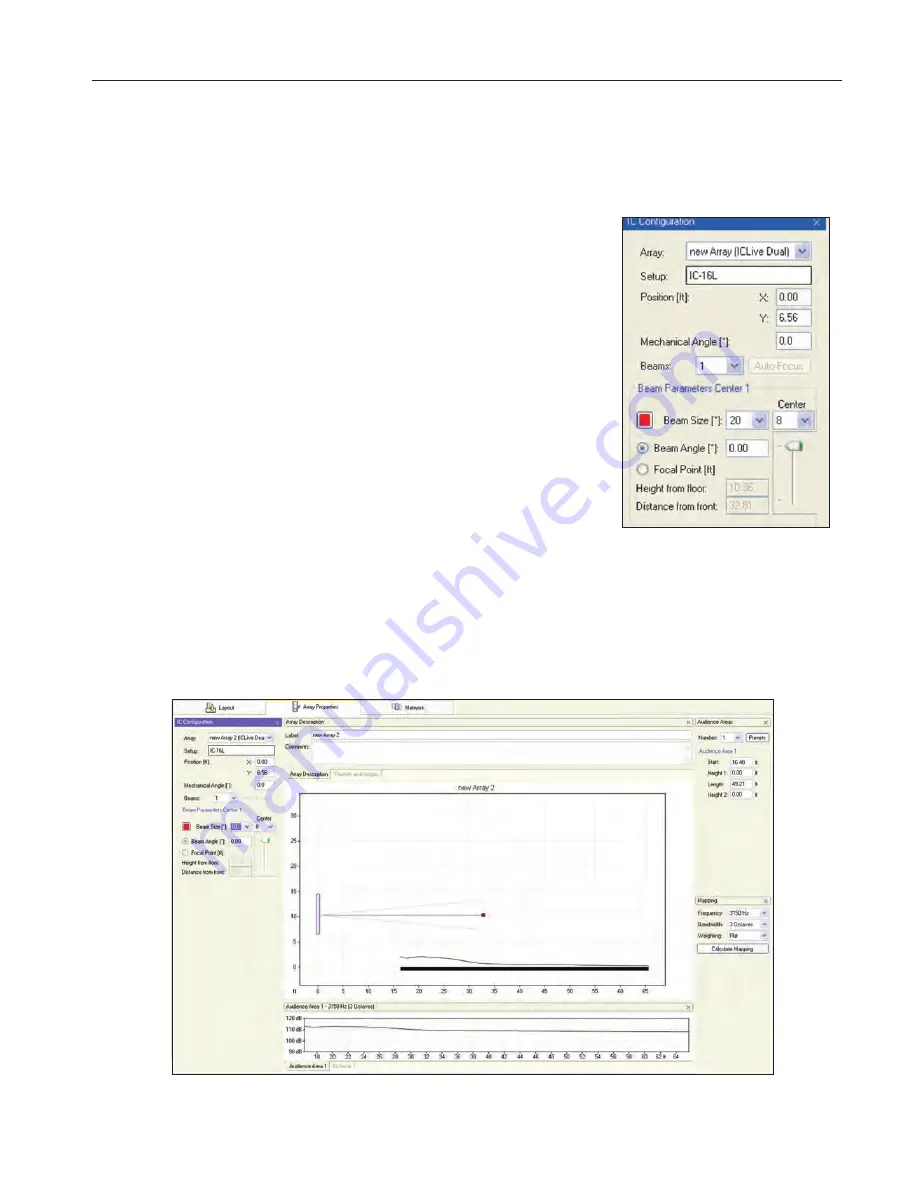
the Array field allows you to select between arrays in multiple array systems.

The field controls the height of the column array by positioning the bottom of the column

above the Floor level (the “0” level) The default position is 6.56 feet (2 meters). The

Mechanical Angle field tilts the column forward or backward (minus [-] numbers tip it back and

plus [+] numbers tilt it forward). This parameter is usually left at 0.0 since the normal position

for Iconyx arrays is flat against a wall and the array’s output digitally steered down onto the

audience area.

The next step is to choose the number of Beams using the Beams field and its associated drop

down menu. One of the unique features of Iconyx steerable arrays is the ability to generate

either single or multiple lobes. We’ll be discussing multiple lobes later in this tutorial, so for now

accept the default single beam configuration. Beam Size lets you choose the Array’s opening

angle which controls the sharpness of the vertical lobe (beam). Try it out using the drop down

arrow. Notice how the opening angle of the array in the graphic varies as you choose different

opening angles.

Beam Angle aims the vertical beam up or down. Try it out by selecting Beam Angle [*], chang-

ing the number and observing its effect. Note that after entering a new number you will need to

press Enter to initiate the change. You will also need to do a new Calculate Mapping to view

the change. The old map will have been wiped out by the program as you made the change.

Note that you can also check Focal Point [ft] and then enter the exact location of the beam’s focal point in Height from Floor and Distance

from Front. Another way to position the beam’s focal point is to use the mouse cursor to grab the end point of the aiming axis and move it to

the desired location. Try it out. It’s easy to do.

The SPL levels in the graphs will change as the setup parameters change.

Содержание IC Live Fixed NON RHAON ICL-F

Страница 1: ...IC Live Users Manual Models ICL F ICL F DUAL Owners Manual USERS MANUAL Assembly Installation Instructions ICL F ICL F DUAL IC Live...

Страница 2: ...his apparatus near water The apparatus shall not be exposed to dripping or splashing and no objects filled with liquids such as vases shall be placed on it 6 Clean only with dry cloth 7 Do not block a...

Страница 3: ...e Software 15 BeamWare 2 15 Canvas 29 Installation 32 Cabling Required 32 Power 32 Hardware Connections 33 Dimensions 34 Audio Digital Control 32 Installation 32 Wall Mounting 36 Suspended Flying 37 S...

Страница 4: ...to assemble the ICL F DUAL is included in the cartons If you ordered a HK ICL series mounting hinge kit with your ICL F array the hinge hardware will be packed with the other hardware If you are not c...

Страница 5: ...ly step is to remove the top of both modules To remove the top remove the eight machine screws from each side of the cabinet and lift the top and its mounting brackets out of the cabinet as shown The...

Страница 6: ...rews supplied Make sure the connectors are fully seated You should hear a click when they seat If necessary use a flashlight to check because if the connectors are not seated properly you may have to...

Страница 7: ...n it will be after the loudspeakers are installed 2 Remove the access plate and locate the Address switches Each 8 channel module will have an access plate Notice that there are 8 orange on off Dip sw...

Страница 8: ...98 are not supported A typical system layout is shown below Notes 1 The audio cable is a conventional twisted pair shielded audio cable It terminates in a 3 pin Phoenix connector and loops from column...

Страница 9: ...ibuted systems for balancing levels during final commissioning Inserting the Iconyx Software CD into the computer s CD ROM drive will open the splash menu screen shown below here INSTALLING THE USB TO...

Страница 10: ...r has not passed Windows Logo testing with the fol lowing message Click on Continue Anyway Windows will finish the driver installation Click on Finish when prompt ed 4 Windows will now find another ha...

Страница 11: ...fter Windows finds the appropriate driver you will be prompted to install it click on Next After Windows finishes installing the driver click Finish when prompted 4 Windows will now find another hardw...

Страница 12: ...ng Manage Click on the Device Manager icon and look for USB to Serial Cable with a yellow exclamation mark You may find it under Universal Serial Bus Controllers Other Devices or Unknown Devices Doubl...

Страница 13: ...0 or higher before proceeding You may down load NETFramework 2 0 from that same location on our website as the BeamWare 2 download or from Microsoft s download site http microsoft com downloads Click...

Страница 14: ...n by clicking on Next C Select the Icon Option you wish to use and then click on Next to contin ue D Click on Install to begin the instal lation E Click on Done to complete the installation Notice tha...

Страница 15: ...a floor plan A quick way to do this is to go to the Project pull down menu select Layout Presets and open the Preset folder Then choose one of the example floor plans For our purposes we ll use the f...

Страница 16: ...r plan drawing and check the horizontal coverage Position the array by grabbing the yellow icon with your mouse cursor and moving it Clicking on the red box which identifies the aiming point allow you...

Страница 17: ...ou added more than one array but didn t select one of them a Select Array prompt will list the arrays you inserted into the project under Layout and ask you to select one of them Note that you can als...

Страница 18: ...t You should know the physical dimensions of the area s you want to cover so the next logical step is to set up the audience area s using the Audience Area section on the right side of the screen To s...

Страница 19: ...d and its associated drop down menu One of the unique features of Iconyx steerable arrays is the ability to generate either single or multiple lobes We ll be discussing multiple lobes later in this tu...

Страница 20: ...below was made using Medium Resolution You also have the opportunity to choose the simulation s Bandwidth its Center Frequency and its Weighting The Frequency section lets you select center frequencie...

Страница 21: ...IC 16L you can select up to a maximum of 8 lobes It s up to four on the IC 8L For now select 2 to add a second beam to the graphic At first glance it may appear that nothing happened since the program...

Страница 22: ...array isn t ideal You can override this warning if you want and the program will still attempt to properly focus all the beams You may however want to try moving the array up or down to see if you ca...

Страница 23: ...ot that the beam opening was narrowed to 25o to obtain a longer throw The next graphic shows an even larger room one with a 125 foot throw Note that the opening angle was reduced to 20o Still the leve...

Страница 24: ...setup screen that allows you to Export save the BeamWare 2 Setup as a rhs Setup file that can easily be imported into EASE and EASE JR It s a simple thing to do just open the EASE Iconyx DLL file int...

Страница 25: ...from two ICL F Columns modules In BeamWare 2 these relationships are stored in the following manner every Column has a unique ID ICID number and every Array has a unique ID Array ID number When a col...

Страница 26: ...termine what Columns are avail able Note that you may have to adjust the Columns in Network section of the window to see the entire listing The next step is to scan the network for Columns Arrays Hard...

Страница 27: ...linked together The easiest way to assign one of the Columns to an Array is to grab it using the cursor and left mouse button and drag it to one of the Column icons Notice that the color of the Colum...

Страница 28: ...work setup window and explore the two setup options we ignored earlier see page 35 The Scan for new Arrays on network option is similar to the Scan for Columns on network option except that it also id...

Страница 29: ...ou also have a choice of initializing the column array to the default setting or of retrieving the column array s previous settings We recommend that you use Retrieve current settings from module sinc...

Страница 30: ...High Pass Filter button inserts a high pass filter into the signal chain and allows you to dial in any low frequency roll off you desire It was preset to 100 Hz with a 24 dB per octave slope Please d...

Страница 31: ...cluded in the program Pressing the Signal Generator but ton will bring up the following screen which allows you to choose the signal s frequency and distribute the signal to the column array Please no...

Страница 32: ...the column s do not include a power on off switch and you will have to make sure an external power on off switch is provided Each module however does include a self restoring circuit breaker as protec...

Страница 33: ...RX TX to TX and so on Recommended RS422 data wire type CAT5E wire is acceptable or for shielded type Belden 9729 has been tested by Renkus Heinz up to 800 meters When using long wire lengths a 120 Oh...

Страница 34: ...Address Number Switches See Page 7 Audio Input Looping Connectors Push To Reset Circuit Breaker Power Connector Universal 100 to 240 Volts 50 60 Hz Signal Limiting Status LEDs See Page 7 Hardware Inp...

Страница 35: ...Dimensions 44 1 4 112 5 cm 47 119 5 cm 95 241 5 cm 44 1 4 112 5 cm 8 20 cm 8 20 cm 7 17 8 cm 48 122 cm 35 IC Live Users Manual ICL F ICL F DUAL...

Страница 36: ...e appropriate Com Port to connect the Fault Monitor to the network and press OK The Monitoring tab in the Options folder allows you to adjust the scan interval time from 5 seconds to 300 sec onds Use...

Страница 37: ...The program checks each amplifier module and reports any failures such as loss of power It also checks the amplifiers operating temperature and reports any over temperature find ings If a fault is de...

Страница 38: ...ither right or left swing away from the wall ICL F columns will have two hinge sec tions ICL F DUAL columns will have three hinge sections The female hinges should be attached to the column and the ma...

Страница 39: ...make sure they are properly made Note The ICL F audio inputs comply with AES Standard 48 2005 on interconnecting grounding and shielding i e pin 1 is connected to chassis NOISE Most noise problems are...

Страница 40: ...ic 7 22 Equipment Requirements 8 Exporting to EASE 24 F Fault Monitoring 36 37 Filters 30 H Hinges 36 I Installation Columns 38 Software 8 to 14 Level control 31 N NetFramework 8 13 Network Setup 25 S...

Страница 41: ...ve down to 800 Hz ICL F DUAL 400 Hz when stacked Five 6 5 inch cone transducers with neodymium magnets Three 1 inch HF titanium nitride compression drivers 8 per module ICL F 48 H x 8 W x 7 D 121 5 cm...

Страница 42: ...19201 Cook Street Foothill Ranch CA USA Phone 1 949 588 9997 Fax 1 949 588 9514 sales renkus heinz com www renkus heinz com RH 657 Rev B March 2010...

Отзывы: