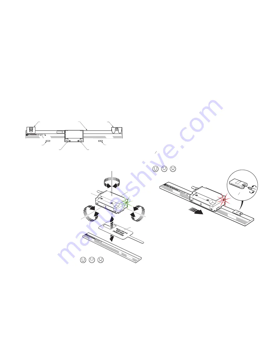
Renishaw RGH40 Скачать руководство пользователя страница 10

Yaw 

0° ±1°

Pitch 

0° ±1°

Roll 

0° ±1°

Rideheight 

0.8 ±0.15 mm

Blue spacer

Reference mark set-up

To ensure uni-directional repeatability, the reference mark requires phasing with the scale in  
the direction of normal datuming operation.
A reference pulse is output in both directions, but repeatability is guaranteed only in the  
phased direction.
Ensure readhead is set-up correctly with a Green LED indication over the full length of travel and 
that the reference mark actuator is fitted correctly.

NOTE: 

It is recommended that a datum procedure is performed as part of any power-up sequence 

to ensure the correct datum position is recorded.

NOTE: 

Reference mark output is synchronised with the incremental channels, giving unit of resolution 

pulse width. For further details see ‘Output specifications’.

Phasing procedure

The readhead must be moved over the reference mark in the direction to be used for the datuming 
operation. The reference mark is phased correctly when the set-up LED flashes Red for 0.25 seconds. 
If it flashes Orange or goes blank, the reference mark adjuster screw should be turned anti-clockwise 
by 

1


8

turn and the procedure repeated until a Red flash is obtained.

1


8

turn

Red  Orange   Blank

Readhead set-up LED flash during 

reference mark traverse only

RGH40 RGS40-G


installation guide

8

Adhesive P and Q limit magnets (A9531-0251) should be mounted using RGG-2 epoxy (A-9531-0342).  
Ensure epoxy is thoroughly mixed prior to use. Allow 24 hours at 20 


°C for full cure.  

Optional bolted limit magnets available, see RGH40 installation drawing for details.

Readhead mounting and alignment

Mounting brackets

The bracket must have a flat mounting surface, enable conformance  
to the installation tolerances, allow adjustment to the rideheight of  
the readhead, and be sufficiently stiff to prevent deflection or  
vibration of the readhead during operation.  
For easier installation, adjust the roll and yaw of the bracket  
with respect to the axis of readhead travel before the  
RGH40 is attached. This can be done with a  
clock gauge and a precision square. 

Readhead set-up

To set nominal rideheight, position readhead spacer  
with ‘L’ shaped aperature under the optical centre of  
the readhead to allow normal LED function during  
set-up procedure. Ensure that the scale, readhead  
optical window and mounting face are clean and  
free from obstructions.

NOTE:

 Ensure readhead fixing screws are tightened  

to 0.5 Nm – 0.7 Nm.
For reliable operation, the set-up LED should be GREEN  
when readhead is moved along the full axis of travel.
An external set-up signal, X, is also available  
on RGH40 readheads for use where the  
LED is not visible. 
See ‘Output specifications’ for details. 

Datum clamp

Scale

Mounting clip

P limit magnet

P limit sensor position

Q limit sensor position

Q limit magnet

Reference mark actuator installation

Refer to RGH40 readhead installation drawing and RGS40-G scale installation drawings for actuator positioning. 
Reference mark actuator (A-9531-0250) should be mounted using RGG-2 epoxy (A-9531-0342). Ensure epoxy is  
thoroughly mixed prior to use. Allow 24 hours at 20 


°C for full cure.

Limit switch installation

Screw mounted or adhesive mounted limit switch actuators are available. Refer to RGH40 readhead installation  
drawing and RGS40-G scale installation drawings for actuator positioning.

Green  Orange  Red

Readhead set-up LED status

Limit switch

Limit switch detection is entirely independent of other readhead functions - the signal is only output 
when the readhead is positioned over the limit switch actuator.

Содержание RGH40

Страница 1: ...Installation guide M 9550 9023 01 A RGH40 RGS40 G linear encoder system...

Страница 2: ...ss scale installation drawing clip clamp mounting 6 Clip clamp mounting installation 7 Reference mark actuator installation 8 Limit switch installation 8 Readhead mounting and alignment 8 Reference ma...

Страница 3: ...tion of this equipment in a residential area is likely to cause harmful interference in which case the user will be required to correct the interference at his own expense NOTE This unit was tested wi...

Страница 4: ...cal encoder scale that provides good immunity against contaminants such as dust fingerprints and light oils However in harsh environments such as machine tool applications protection should be provide...

Страница 5: ...es optical and reference mark centreline Roll tol 1 Q limit magnet A 9531 0251 Mount dimple up for Q Optional bolted limit magnet P A 9550 0047 Q A 9550 0048 Mounting ledge or top surface of bracket f...

Страница 6: ...6 5 2 9 4 10 3 18 8 5 4 05 17 5 25 5 12 5 27 5 ML 47 ML 44 L ML 14 5 L 25 n 1 4 9 2 9 10 12 RGG 2 2 part epoxy usually coincident with user selected scale datum Double sided adhesive tape Bolted P lim...

Страница 7: ...to cure fully then clean scale using Renishaw scle wipes A 9523 4040 or a clean dry lint free cloth Adhesive mounting installation 2 Mark area for epoxy on adhesive tape 1 RGH40 RGS40 G installation...

Страница 8: ...x 6 5 14 5 M3 x 0 5 x 6 5 23 5 0 1 34 4 10 3 18 8 5 4 05 17 5 25 5 12 5 27 5 5 5 Datum clamp Mounting clip 4 9 2 9 Dimensions and tolerances in mm RGS40 G glass scale installation drawing clip clamp m...

Страница 9: ...ean dry lint free cloth M 9550 0057 gap setting shim 4 Ensure scale can move so free to expand contract 1 2 mm 1 2 mm M 9550 0057 gap setting shim M 9550 0061 datum pad RGH40 RGS40 G installation guid...

Страница 10: ...able conformance to the installation tolerances allow adjustment to the rideheight of the readhead and be sufficiently stiff to prevent deflection or vibration of the readhead during operation For eas...

Страница 11: ...way D type plug L 12 way circular V 12 way circular coupling W 16 way in line connector X Power 5 V Brown 4 2 2 A Brown link 5 12 12 M 0 V White 12 10 10 B White link 13 11 11 N Incremental signals V1...

Страница 12: ...ers must ensure they comply with the lowest recommended counter input frequency Encoder velocity m s Resolution m x 4 safety factor Function Signal Colour 15 way D type plug D 16 way in line connector...

Страница 13: ...d from each other If the inner and outer shields are connected together this will cause a short between 0 V and earth which could cause electrical noise issues Electrical connections Grounding and shi...

Страница 14: ...P Resolution S A B Z Inverse signal not shown for clarity Synchronised pulse Z duration as resolution S Repeatability of position uni directional maintained within 10 C from temperature at time of pha...

Страница 15: ...ealing IP50 Acceleration Operating 500 m s2 3 axes Shock Non operating 1000 m s2 6 ms sine 3 axes Vibration Operating 100 m s2 max 55 Hz to 2000 Hz 3 axes Mass Readhead 50 g Cable 38 g m Cable 12 core...

Страница 16: ...our main website at www renishaw com contact M 9550 9023 01 RENISHAW and the probe symbol used in the RENISHAW logo are registered trade marks of Renishaw plc in the United Kingdom and other countrie...

Отзывы: