


RSK+RX71M
5. User Circuitry
R20UT3217EG0100 Rev. 1.00
Page 20 of 71
Jan 23, 2015
5.7
USB Serial Port
A USB serial port implemented in another Renesas low power microcontroller (RL78/G1C) is fitted on the
RX71M Serial Communications Interface (SCI) module. Multiple options are provided to allow the selection of
the connected SCI7 port. Connections between the USB to Serial converter and the microcontroller are listed
in
Signal Name
Function
MCU
Port
Pin
TXD1*
1
SCI1 Transmit Signal.
PF0
35
RXD1*
1
SCI1 Receive Signal
PF2
31
TXD2*
1
SCI2 Transmit Signal.
P50
72
RXD2*
1
SCI2 Receive Signal
P52
70
A-TXD7
SCI7 Transmit Signal.
P90
163
A-RXD7
SCI7 Receive Signal
P92
160
RS232TX*
1
External SCI Transmit Signal.
-
-
RS232RX*
1
External SCI Receive Signal.
-
-
RXCTS*
2
Clear To Send
P41
171
RXRTS*
2
Request to Send
PJ5
11
Table 5-6: Serial Port Connections
*
1
. This connection is a not available in the default RSK+ configuration - refer to §6 for the required
modifications.
*
2
. CTS & RTS control is not supported on this RSK+.
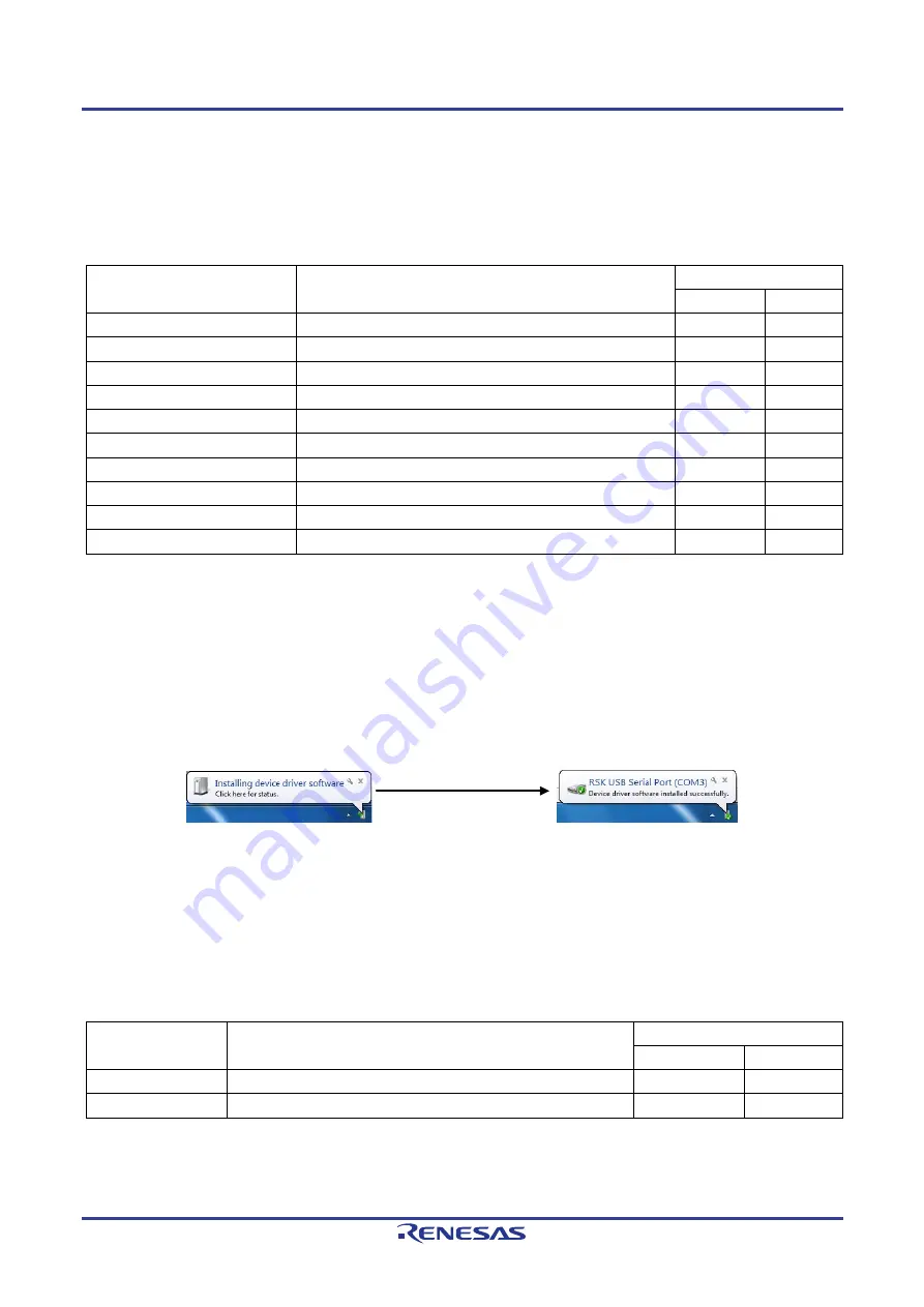
When the RSK+ board is first connected to a PC running Windows with the USB/Serial connection, the PC will
look for a driver. This driver is installed during the installation process, so the PC should be able to find it. The
PC will report that it is installing for a driver and then report that a driver has been installed successfully, as
shown in
. The exact messages may vary depending upon operating system.
Figure 5-2: USB-Serial Windows Installation message
5.8
Controller Area Network (CAN)
A CAN transceiver IC is fitted to the RSK+ board, and connected to the CAN MCU peripheral. For further
details regarding the CAN protocol and supported modes of operation, please refer to the RX71M Group
User’s Manual: Hardware.
The connections for the CAN microcontroller signals are listed in
below.
CAN Signal
Function
MCU
Port
Pin
CTX0
CAN Data Transmission.
P32
29
CRX0
CAN Data Reception.
P33
28
Table 5-7: CAN Connections
Содержание RX71M
Страница 71: ...R20UT3217EG0100 RX71M Group ...