8
w2
u2
v2
w2
u2
v2
w2
u2
v2
u1
v1
w1
u1
v1
w1
u1
v1
w1
L1
L2
L3
L1
L2
L3
L1
L2
L3
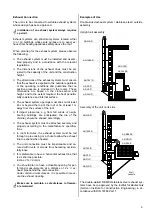
Gas Connection
Depending on the capacity of the unit, the required
quantity of gas must always be available and the neces-
sary gas pressure present during unit operation.
Gas pressure regulators and shut-off valves are to be
supplied by the manufacturer.
The line cross-section must correspond to the connec-
tion values of the units, the total line resistance and the
gas pressure.
G
Prior to initial operation, the gas supply line must be
thoroughly cleaned and tested for impermeability!
Burner Installation
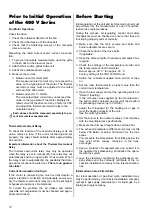
The forced-air burner supplied by the manufacturer is
attached to the front of the unit with a clamp flange.
You must observe the following:
◊
Only forced-air burners with automatic burners that
have a 5 sec. safety period may be used.
◊
It is not necessary to limit the capacity in single-
stage burner operation for the warm air generator.
◊
The burner must be adjusted to the full heat load of
the unit.
◊
The combustion chamber may not be operated be-
low capacity.
◊
The exhaust temperature may not fall below 160 de-
grees Kelvin above the room temperature.
Condensation accumulation.
◊
Follow the operating instructions of the burner sup-
plied by the manufacturer.
◊
If burners from other manufacturers are used, they
must be checked for compatibility with the unit.
Electrical Installation
The electrical connection of the units may only be per-
formed by authorised personnel in accordance with the
relevant regulations (including any local ones).
An easily accessible emergency switch must be at-
tached in the setup room.
The emergency switch must be protected from unau-
thorised use.
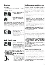
Thermostat Connection
The room thermostat (accessory) or day/night regulator
(accessory) is connected via special connections.
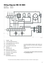
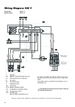
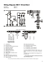
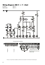
Please follow the appropriate wiring diagram for con-
nection.
The room thermostat (accessory) must be placed in the
most ideal location in the room for regulating tempera-
ture.
Important Instructions for Unit Assembly
Make sure to observe the following general instructions
as well.
◊
Operating devices for the units and the fuel supply
must be able to be operated directly from the
ground.
◊
The operator must provide any support material nec-
essary for monitoring, maintenance and repair work.
The thermostat sensor may not be exposed directly to a
particularly cold or warm air current.
The process is the same for installation of an automatic
day/night temperature regulator (accessory).
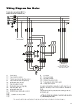
Fan Motor Connection
The units are completely wired at the factory.
In the event of changes or if the fan is replaced, make
sure to connect the motor and condenser to one an-
other properly and ensure that the rotational direction of
the motor is correct.
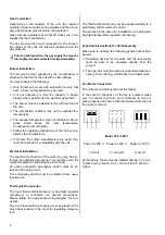
Motor 230 / 400 V
Power 3x 400 V
Power 3x 400 V
Power 3x 230 V
Y circuit
Y /
∆
circuit
∆
circuit
At the factory, the motors are initiated directly in Y up to
3.0 kW and by means of a Y /
∆
circuit for 4.0 kW and
higher.


