background image

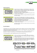
External operation

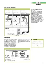
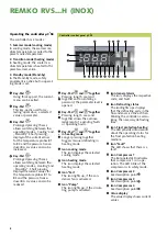
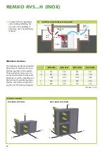
Key-Pad functions

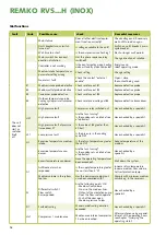
External operating contact C / H

Standard means of switching on or off of the system is done manually 

using the controller or using the cabled remote control available as an 

accessory. Parameters must be changed if the system is to be activated 

externally by means of an electrical switch. 

Parameter H 07 activates the external Controller.  

With regard to the subject of switching, please read the respective chap-

ter under “electrical connection”.

Operating using the controller is no longer possible once the parameter-

shave been changed.

Standard means of switching between the heating and cooling modes 

is done manually using the controller or using the cabled remote control 

available as an accessory. A parameter must be changed if the operating 

mode is switched externally by an electrical switch. 

Parameter H 06 activates the external switching. 

With regard to the subject of switching, please read the respective chap-

ter under “electrical connection”. 


Operating using the controller is no longer possible once the parameters 

have been changed.

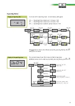
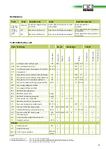
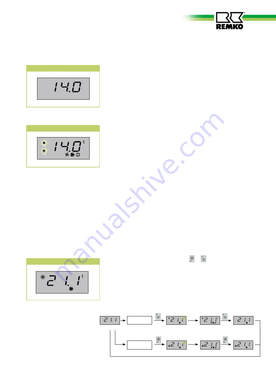
External enabling contact

Activate or deactivate the unit with the   or   key-pad by pressing 

for more than 5 seconds. The set operating mode appears in the display 

(cooling or heating icon). 
The unit has three modes: Stand-By mode, Summer mode (cooling mode)

and Transition mode (heating mode only for systems with HP function). In 

Stand-By mode no symbol is shown only the current value is displayed. All 

fault reports and frost protection resistors are active. 

Note: Other functions can be programmed for the icon by changing the 

       parameters.

Setting the operating mode

Cooling mode

Heating mode

Operating mode Stand-By

HEATING 

MODE

COOLING 

MODE

5 sec.

5 sec.

min. 5 sec.

min. 5 sec.

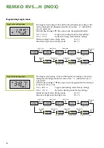
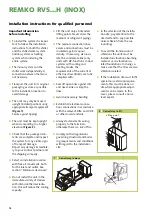
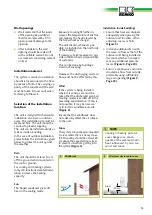
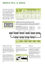
Operating the unit is carried out using the controller’s key-pads. Checking current value or putting in the target 

value for the summer mode (cooling mode) and the transition mode (heating mode) only for systems with (HP-

function) is done without the use of a password. 

Qualified personnel who are authorised to use a passwords, can access submenus to change the systems con-

figuration. All changes to the parameters must be documented and kept permanently by the system. 


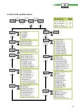
The following diagrams provide simplified illustrations of the operating functions.

9

Содержание RVS 100H INOX

Страница 1: ...OX RVS 60H RVS 75H RVS 100H RVS 150H RVS 60H INOX RVS 75H INOX RVS 100H INOX RVS 150H INOX Air cooled Chiller with Heat Pump function Air cooled Chiller with Heat Pump function in Stainless Steel Oper...

Страница 2: ......
Страница 3: ...Warranty 5 Transport and packagin 5 System description 5 6 System configuration 7 Operation 7 13 Care and maintenance 14 Shut down 14 Trouble shooting and customer service 15 17 Installation instructi...

Страница 4: ...curely on suitable surfaces and in an upright position Stationary systems must be permanently installed for operation Modification of the system or its components supplied by REMKO is not permitted an...

Страница 5: ...unit an air to water chiller takes heat out of the operating medium to be cooled water or a mixture of water and glycol within a closed medium cycle in the evaporator plate heat exchanger and gives it...

Страница 6: ...pillary tube 14 Thermal expansion valve cooling 15 Probe medium intake 16 Probe medium outlet 17 Probe condenser 18 Pressure transducer Construction 1 1 3 3 4 4 5 5 7 7 17 17 8 8 9 9 14 14 11 11 18 18...

Страница 7: ...ceiling depending on where the unit is mounted For each of the different systems a minimum flow volume and a mini mum medium volume is needed for safe operation Chilled water system System configurat...

Страница 8: ...t no operat ing mode is set Key Pad Using this key pad the current menu can be exited Key Pad This key pad is used for se lecting open close a selected value or parameter Key Pad Prolonged pressing 5...

Страница 9: ...the parameters have been changed External enabling contact Activate or deactivate the unit with the or key pad by pressing for more than 5 seconds The set operating mode appears in the display cooling...

Страница 10: ...g r 04 can be displayed and changed under the menu item r without the use of a password With the Key Pad or the value can be changed within the limits set in the factor r15 r16 r 03 40 0 C Target valu...

Страница 11: ...ary for mainte nance 1670 operating hours 0 operating hours short term short term min 5 sec min 5 sec min 5 sec repeated repeated repeated repeated short term short term short term Display of the oper...

Страница 12: ...ports The controller shows the current faults one after the other Simultaneously pressing key pad and can after the fault has been corrected be used to confirm the correction Faults are saved in a fau...

Страница 13: ...16 Calibration B4 21 Digital filter 22 Input limit 23 Unit of measurement C F A01 Target value frost protection A02 Hysteresis frost protection A03 Time delay frost protection A04 Target value medium...

Страница 14: ...ervice life Prior to performing any work The system must be switched off and isolated from the power supply and secured to prevent accidental switch on CAUTION Wearing appropriate protec tive clothing...

Страница 15: ...he start up delay max 360 sec the compressor should then start The display blinks and alternately shows an alphanumeric code and the temperature value One or more protective devices have responded Che...

Страница 16: ...fans turning Is the condenser s air intake free of obstacles Have checked by a specialist High pressure fault at pressure tranceducer PT Is the value at B4 greater than 40 bar Have checked by a specia...

Страница 17: ...e ID3 3 hrs 3 hrs HP 2 x on 1 min HP1 Tranceducer cooling cycle excess pressure Bn V x PS Bn V x x x LP1 Pressure switch ND cooling cycle ID4 3 hrs 3 hrs LP 3 x x tC1 Overload cycle 1 P08 13 x x x tEr...

Страница 18: ...t pipings The medium connection lines valves and connections must be insulated against vapour density If necessary also insu late the condensate line only units with HP function In dual systems with c...

Страница 19: ...The unit should whenever pos sible be installed on the north side of the building If necessary take measures to pro vide sufficient shade responsibility of customer This can be done by building a sma...

Страница 20: ...l Chiller Warm air Light well Additional fan 5 Installation inside buildings cooling mode Minimum clearances The following illustration indicates the minimum clearances for trou ble free operation of...

Страница 21: ...other parts of the building 4 Connect the medium lines Separating the Transport pallet The system is supplied with a pallet for the purpose of transportation Remove this before installation Transport...

Страница 22: ...lustration and carry out the correct installation of the drain line Local disposal regulations must be observed if glycol is used Pipe routing RVS 60H RVS 75H free pipe routeing possible free pipe rou...

Страница 23: ...s only straight flow through fittings should be used When designing the layout it must be taken into account the large flow volumes in the systems high pressure losses in connection with water glycol...

Страница 24: ...ct data sheets for the glycol type being used This mixture ensures frost protec tion to 20 C at lower tempera tures an ice porridge forms which has no more expansion effect The toxicologically harmles...

Страница 25: ...ontent is recom mended Either the medium lines can be oversized or an additional storage tank installed A storage tank should as a rule be provided if the minimum me dium volume of the system is not r...

Страница 26: ...interior unit is not necessary A three phase main switch must be installed in the power supply outside of the unit Electric connections must be installed permanently in accordance with the regulation...

Страница 27: ...cable to the relive strain 3 Then connect the cable in ac cordance with the connection diagram 4 Check that the poles are con nected correctly 5 Replace all parts which were short term short term sho...

Страница 28: ...al enable cooling heating mode can be used after switching Cabled remote control Accessories The cable remote control is used for example for the querying programming or operation of the unit from a r...

Страница 29: ...e continuous condensate draining at low ambient tempera tures Phase sequence relay FCR only RVS 100H RVS 150H The phase sequence relay controls the phase sequence of the power supply The relay will no...

Страница 30: ...r A2 Fan speed controller B1 Probe medium intake B2 Probe medium outlet B3 Probe condenser EV Reverse flow valve FCR Phase sequence relay FL Flow switch FR Motor overload protection switch HP High pre...

Страница 31: ...itch HP High pressure switch LP Low pressure switch M1 Compressor M2 Circulation pump M3 Condenser fan 1 M4 Condenser fan 2 RC1 Compressor crank case heater RF1 Defrost heater TA1 Transformer 230 24V...

Страница 32: ...metre difference in altitude geodetic al titude The value measured at the highest point is identified as the none circulating pressure The position of the unit in the system is decisive in the calcula...

Страница 33: ...um cycle Set the circulation pump s flow volume Checking the cooling cycle Checking the cooling cycle for adequate oil coolant Check the cooling cycle for leaks Expansion vessel The preliminary pressu...

Страница 34: ...ll the required values in the commis sioning report and check the safety functions 7 Check the system control using the functions described in the Operation chapter Working test for heating mode only...

Страница 35: ...dance with the different unit sizes they are available as accessories Their dimensions must be added to the dimensions listed above 1115 625 430 470 470 470 650 430 850 430 1245 1115 825 1115 1220 35...

Страница 36: ...dify the dimensions and constructional design as part of the ongoing technical development process Exploded view RVS 60H RVS 75H 4 5 6 29 7 8 10 18 19 22 11 12 2 1 24 25 26 27 28 17 23 20 21 14 15 16...

Страница 37: ...on pump 1111412 1111413 16 Flow switch 1111465 1111415 17 Medium storage tank 1111417 1111418 18 Controller covering 1111420 1111420 19 Controller C 2 SE 1111421 1111421 19 Controller C 2 SE programme...

Страница 38: ...0H We reserve the right to modify the dimensions and constructional design as part of the ongoing technical development process 4 5 6 29 17 7 7 8 8 10 18 19 22 11 12 2 1 24 25 26 27 28 23 20 21 14 15...

Страница 39: ...essure transducer cooling cycle 1111410 1111410 14 Expansion vessel 1111411 1111411 15 Circulation pump 1111414 1111414 16 Flow switch 1111415 1111415 17 Medium storage tank 1111419 1111419 18 Control...

Страница 40: ...0 7 48 6 74 11 93 11 32 10 70 9 74 16 47 15 77 15 07 14 21 14 7 03 6 55 6 07 5 58 9 01 8 37 7 72 6 97 12 34 11 73 11 11 10 17 16 85 16 17 15 49 14 66 15 7 17 6 70 6 23 5 75 9 27 8 59 7 92 7 17 12 70 1...

Страница 41: ...79 9 91 2 94 RVS 100H RVS 150H Air intake temperature relative air humidity C r F 5 90 0 90 5 85 7 85 10 85 15 80 5 90 0 90 5 85 7 85 10 85 15 80 Medium intake QH kW PE kW QH kW PE kW QH kW PE kW QH...

Страница 42: ...2 kW 2 16 2 75 4 05 5 40 Elec nominal current consumption heating 2 A 9 84 13 15 7 22 9 24 Elec starting current LRA A 33 41 61 67 Operating medium max 35 ethylene glycol max 35 propylene glycol Opera...

Страница 43: ...Co KG Air conditioning and heating technology Im Seelenkamp 12 D 32791 Lage Equipment machinery Implementation Air cooled water chiller with heat pump function Series Model REMKO RVS 60H RVS 75H RVS 1...

Страница 44: ...ists REMKO field staff are more than just sales representatives above all they must act as advisers to our customers in air conditioning and heating technology Customer Service Our equipment operates...

Отзывы: