18
11. Now tighten the bolts using 2 hexagonal wrenches
that have a large enough opening.
12. Use a second wrench to apply counterpressure
when tightening.
13. Insulate the installed refrigerant lines including the
connector against heat.
Only use insulation hoses sealed against diffusion
that are suitable for this temperature range.
14. Connect the condensation and control lines.
If you also need a condensation pump, install it be-
forehand.
15. If it is not possible to run the condensation line
through the same guideway, make sure that the
condensation can drain freely at all times.
16. Lay the refrigerant lines from the indoor unit to the
outdoor part.
Make sure that they are adequately secured. Take
steps, if necessary, to ensure oil recirculation!
17. Place the control line in the same line guideway.
18. Remove the protective caps supplied and the swivel
nut caps of the shut-off valves and use these for
continued assembly.
19. Before you flare the refrigerant lines, ensure that
there is a swivel nut on the hose.
Only use the factory-installed swivel nuts.
20. Connect the refrigerant lines to the outdoor part as
described above.
G
If the length of the connection line is longer than 5
m, refrigerant must be added to the system during
initial operation.
See the section Adding Refrigerant.
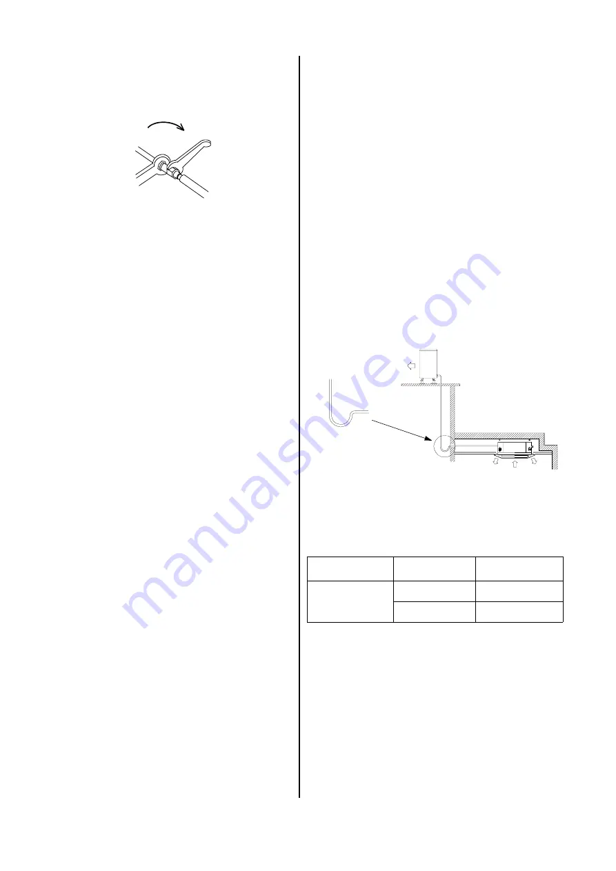
Oil recirculation
If the outdoor part is set up at a higher level than the in-
door unit, appropriate steps must be taken for oil recir-
culation.
This is usually accomplished by creating an oil elevation
arc that is installed every 2.5 meters of line going up.
Impermeability test
Once all connections have been made, the manometer
station is connected to the corresponding valve connec-
tions as described below:
blue = large valve = suction pressure,
After the connection has been made, an impermeability
test is conducted using dry nitrogen.
The connections that have been established are
sprayed with a leak locator spray to test for imperme-
ability. If bubbles appear, the connection was not made
properly. Tighten the bolts more firmly or, if necessary,
create a new flare.
After the impermeability test has been successfully con-
ducted, any excess pressure is removed from the refrig-
erant lines and the vacuum pump put into operation to
create a vacuum in the lines.
We recommend using a two-speed vacuum pump with
an absolute final partial pressure of at least 0.01 mbar
at a pump capacity of a min. of 1.5 m³/h.
Procedure:
1. Remove the vacuum pump and connect the filling
cylinder or the refrigerant container.
2. Place the open cylinder/container on a scale and
calibrate the scale to zero.
3. Create a vacuum in the hose at the height of the ma-
nometer distribution pipe.
4. Determine the required amount based on the infor-
mation in the table above and open the suction pres-
sure side of the manometer to begin the filling proc-
ess.
5. Close the manometer valve when the appropriate
amount has been added.
Length of the line
Diameter of the
injection line
Additional quantity
per m
5 m up to and
including a max.
of 15 m
9.52 mm Ø
/
3
/
8
‘‘
18 g for RKS
9.52 mm Ø
/
3
/
8
‘‘
30 g for RKM
Adding refrigerant
The additional refrigerant amount required is based on
the length (5 m and higher) and the diameter of the
pressure line.
Counterpressure
open-end wrench 1
Counterpressure
open-end wrench 2
G
A vacuum with a minimum of 0.05 mbar must be
created!
How long it takes to create the vacuum is based on the
hose line volume of the indoor unit and the length of the
refrigerant lines. However, this process takes a mini-
mum of 30 minutes.
Once foreign gases and moisture have been completely
removed from the system, the manometer station
valves are closed and the valves of the outdoor part are
opened.
Radius
min. 50 mm
Oil elevation arc in the
suction line to the outdoor
part 1x for every 2.5 m
Outdoor part
Indoor unit
Содержание RKV 13 C
Страница 2: ......


