REMKO AT 25 Скачать руководство пользователя страница 5

Safety temperature limiter (STB) 

The safety temperature limiter (STB) interrupts the 
burner operation in the event of overheating and locks 
all unit functions. 

If the safety temperature limiter has triggered, the cause 
of the disturbance must first be localised and elimi-
nated. Resetting via the "RESET" key is only possible 
after the sensor has cooled to below ca. 90 °C. 

The safety temperature limiter is unlocked by pressing 
the reset key. 

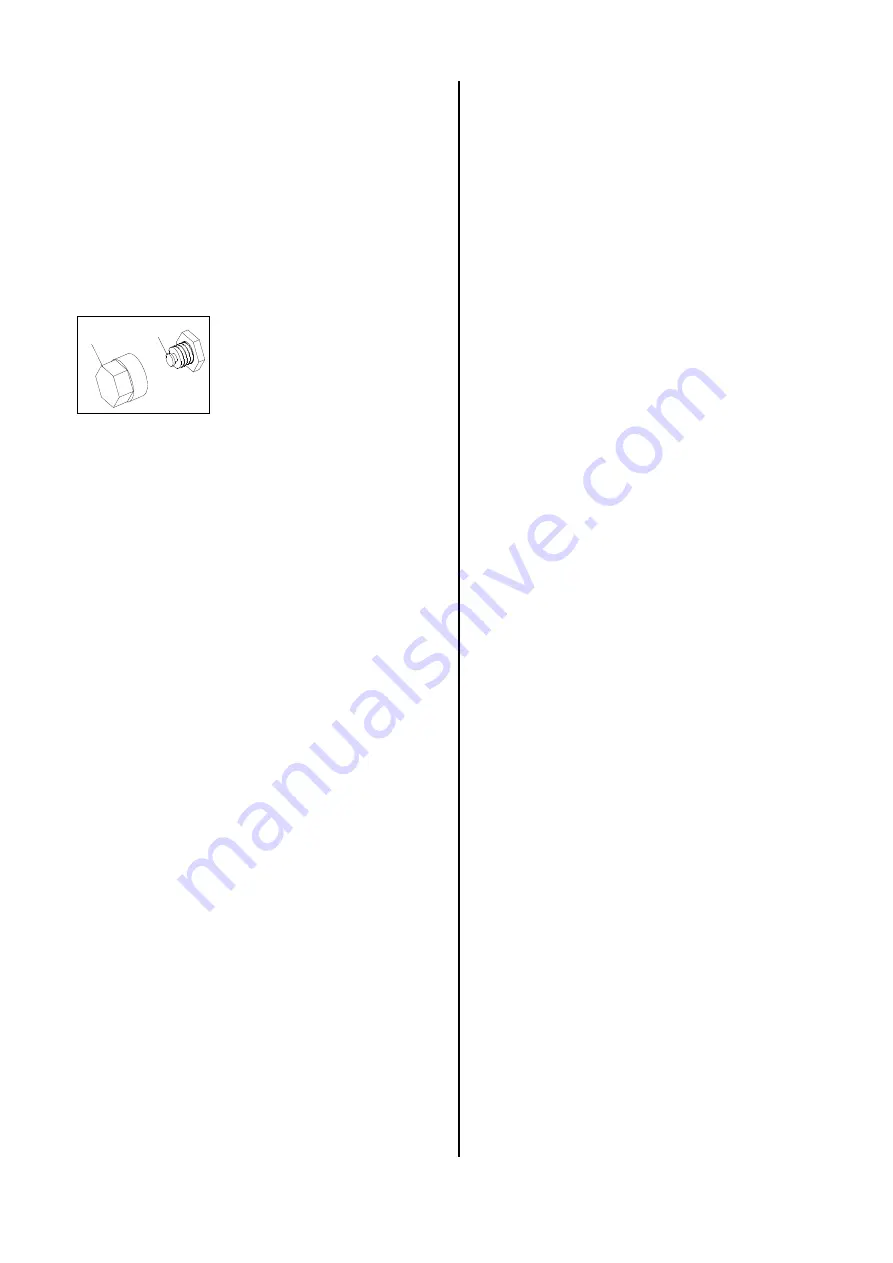
1.   Detach the protection cap 

1

2.   Press the reset key 

2.


3.   Replace the protection cap. 

Provision for Air Heaters 

 
For the deployment of the unit, the relevant guidelines 
must be observed 

1.      Operating personnel 

1.1    The unit must only be operated by persons who 

have been trained in its operation. 


2.      Installation 

2.1    The unit must be installed so that it can stand in a 

stable position. 

2.2    The unit must be installed and operated in such a 

way that the employees are not  exposed to the 
danger of exhaust gases and radiant heat and that 
the occurrence of fires is ruled out. 

2.3    The unit may only be installed and operated in 

rooms if a quantity of air sufficient for the combus-
tion is supplied to the unit and the exhaust gases 
are removed to the exterior. 
A natural air supply sufficient for the combustion is 
present if e.g. 

The room contents in m² correspond with at least 
10 times the nominal heat load in kW of all the 
units operating in the room and if windows and 
doors ensure a natural change of air. 

2.4    In deviation from point 2.3, the unit can be oper-

ated without an exhaust system in rooms if these 
rooms have a sufficient air supply and are well ven-
tilated and if materials harmful to health do not 
reach an unhealthy concentration. 

2.5    A good natural air supply and ventilation is the case 

if e. g. 
The room contents in m² correspond with at least 
30 times the nominal heat output of all units operat-
ing in the room and a natural change of air is en-
sured through windows and doors, or


openings which are not lockable are present in the 
region of ceiling and floor for the air supply and for 
out going air and the size of these openings in m² 
corresponds with at least 0.003 times the nominal 
heat output in kW of all units operating in the room. 

2.6    The unit must not be installed or operated in rooms 

and areas where the danger of fire or explosion ex-
ists. 


3.      Room drying 

3.1    In deviation from point 2.3, in order to dry rooms 

with an air supply sufficient for the combustion, 
heating units can be operated without the exhaust 
gases being removed to the exterior. In these 
rooms, the permanent presence of persons is for-
bidden. Signs on the entrances to the rooms must 
indicate that this is forbidden. 


4.      Examination 

4.1    The unit must be tested by an expert as to its work 

safety specific condition in accordance with the re-
quired deployment conditions but at least once an-
nually. 

4.2    The exhaust values of the burner must be checked. 
 

5.      Monitoring 

5.1    When starting work, the persons commissioned 

with the operation of the unit must check the unit 
for obvious defects or deficiencies on the opera-
tional and safety mechanisms and check that the 
safety mechanisms are present. 

5.2    If defects or deficiencies are discovered, the super-

visor must be informed. 

5.3    In the case of defects or deficiencies which en dan-

ger the operational safety of the unit, its operation 
must be terminated. 


6.      Installation in closed, well aerated rooms with-

out connection to a chimney


6.1    The operation of the units is admissible when the 

minimum air quantity needed for combustion and 
mentioned in point 2.5 is supplied. 

6.2    A safe exhaustion of the waste gases is to be en-

sured to exclude inadmissible pollution. 

Fresh air

 is fed from 

below

waste gases

 are exhausted towards the 

top


7.      Correct usage 

7.1    The unit are to be used only for heating purpose in 

industrial or commercial application because of their 
construction and equipment. 

7.2    If specification of the manufacturer or legal regula-

tions, are not followed or if unauthorised changes 
are made on the unit, the manufacturer is not liable 
for resulting damages.


Содержание AT 25

Страница 1: ...REMKO powerful like a bear Edition GB M04 Operation Technology Spare Parts REMKO AT 25 Automatic oil heater ...

Страница 2: ......

Страница 3: ...10 Wiring diagram 10 Troubleshooting 11 Exploded view 12 Spare part list 13 Maintenance log 14 Automatic oil heater REMKO AT 25 Make sure to read these instructions carefully before starting using the unit Our guarantee will become void when the unit supplied by us is used and installed for inadequate purposes or maintained incorrectly etc or if it is changed without our prior consent Subject to a...

Страница 4: ...rner with optical flame monitoring a low mainte nance axial ventilator a connection cable with plug a room thermostat socket and a fivefold filter system The unit complies with the basic safety and health re quirements of the relevant EU stipulations and is reli able and simple to operate The unit can be used e g in the following areas for drying new buildings for point heating of outdoor workplac...

Страница 5: ...nd doors or openings which are not lockable are present in the region of ceiling and floor for the air supply and for out going air and the size of these openings in m corresponds with at least 0 003 times the nominal heat output in kW of all units operating in the room 2 6 The unit must not be installed or operated in rooms and areas where the danger of fire or explosion ex ists 3 Room drying 3 1...

Страница 6: ...he units are generally to be operated in accordance with the safety rules the building code of the land con cerned and the fire protection code Avoid under or overpressure in the room where the unit is installed as this would result in combustion troubles Suction and blow out cross sections may not be re duced It is prohibited to connect conduits or hoses to the unit blow out opening Make sure tha...

Страница 7: ...It is not possible to get rid of paraffin discharge which is already present using the tank heating The requirement for this is the cleaning of the entire fuel system G The unit is to be installed only in well aerated rooms but not in living rooms or similar recreation rooms 1 Put operating switch 1 into 0 position OFF 2 Connect unit plug to a suitable mains socket 230V 1 50 Hz Connect the unit wi...

Страница 8: ...e a long service life and trouble free operation After each heating period or even earlier depending on the deployment conditions the entire unit including combustion chamber and burner head must be cleaned of soot sediments dust and dirt The oil filters must also be cleaned replaced at least once a year or depending on the degree of contamina tion of the fuel frequently G Setting and maintenance ...

Страница 9: ...ustment of air slide plate Fine adjustment of air slide plate by means of CO2 indi cator and soot pump CO2 value approx 10 13 Soot figure 0 1 by Bacharach 4 When maintenance has been carried out re assemble all parts carefully in reverse order 5 Pre set air flow plate air slide plate and the ignition electrode distance according to the approximate indi cations 4 2 3 4 8 air slide plate air flow pl...

Страница 10: ...re counter clockwise reduce the pressure The required pump pressure is determined according to the heating capacity please refer to unit type plate and to the nozzle size The pressure setting screw A is to be secured with the counter nut B after having set the pressure Fuel Pump The standard type of the pump runs in a system of 1 pipe The required fuel is sucked in through the suction line S For t...

Страница 11: ...f ignition electrodes or damaged insulation Adjust correctly resp replace it 13 Air flow plate of the burner head is misadjusted resp dirty Adjust correctly by means of CO2 indicator and soot pump CO2 10 13 and soot figure by Bacharach 0 1 14 Solenoid valve does not open Check solenoid valve resp replace if necessary A click should be heard during switching on off The safety temperature limiter ha...

Страница 12: ...12 Exploded View We reserve the right to make modifications in dimensions and construction in the interests of technical progress See fig A See fig B Fig A Fig B 74 ...

Страница 13: ...ition cable kit 1102159 40 ignition electrode 1102132 41 traction relief 1108325 No Description Ref No 42 thermostat socket 1101018 43 bridge circuit plug 1101019 44 protective socket big 1101615 45 capacitor 1102907 46 connection cable solenoid valve 1102825 47 hose connection fitting 1102109 48 fuel pump with solenoid valve 1103717 49 copper pipe 4 mm cpl 1102315 50 angle clutch 1 8 x 4 1102112 ...

Страница 14: ...ing screws Electric safety inspections Test run Maintenance Log Model Model No Setting and maintenance work is to be carried out only by authorised specialists Remarks 1 Date 2 Date 3 Date 4 Date 5 Date Signature Signature Signature Signature Signature 6 Date 7 Date 8 Date 9 Date 10 Date Signature Signature Signature Signature Signature 11 Date 12 Date 13 Date 14 Date 15 Date Signature Signature S...

Страница 15: ......

Страница 16: ...REMKO GmbH Co KG Klima und Wärmetechnik D 32791 Lage Im Seelenkamp 12 D 32777 Lage PO Box 1827 Phone 49 5232 606 0 Fax 49 5232 606260 ...

Отзывы: