REMKO - powerful like a bear.
Edition GB – M04
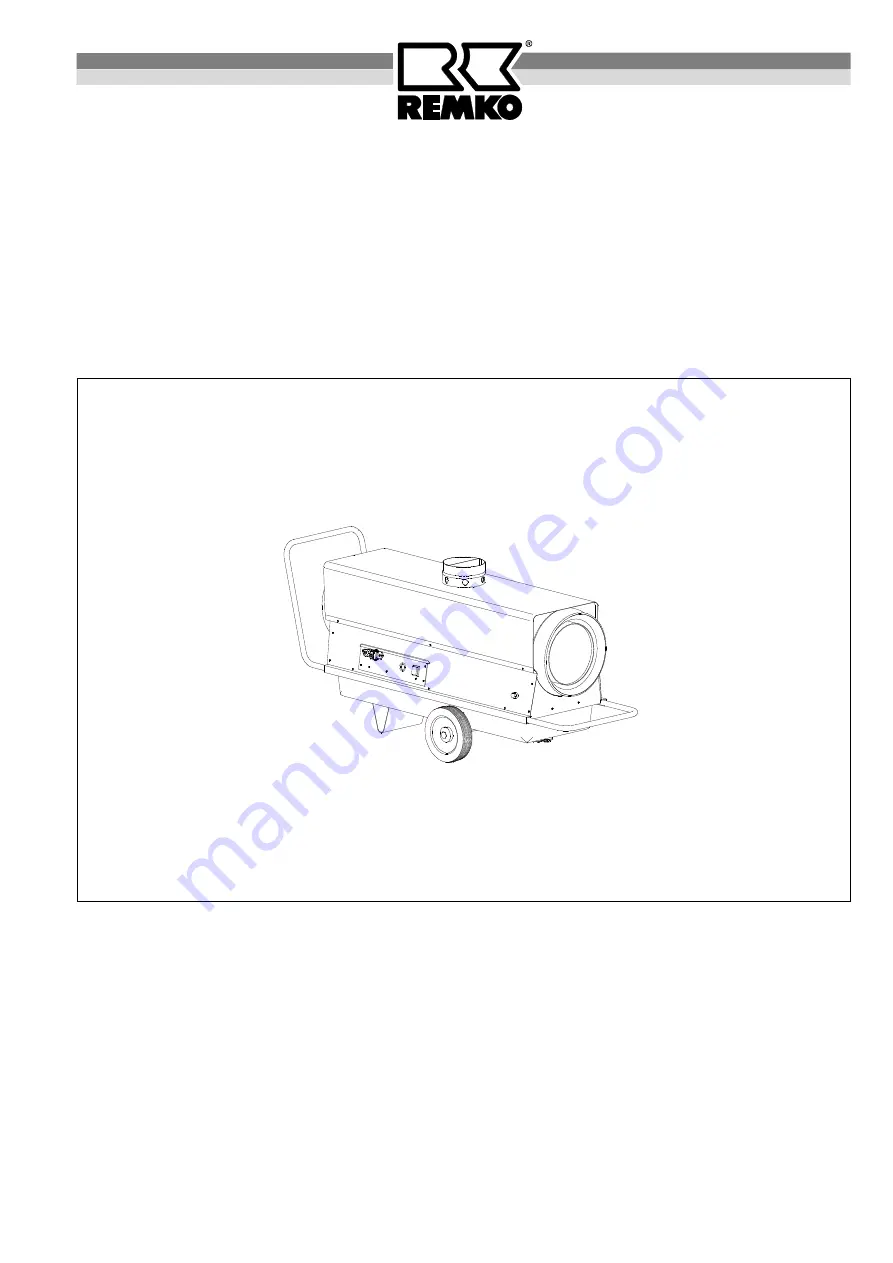
Operation
Technology
Spare Parts
REMKO AT 25
Automatic oil
heater
Страница 1: ...REMKO powerful like a bear Edition GB M04 Operation Technology Spare Parts REMKO AT 25 Automatic oil heater ...
Страница 2: ......
Страница 3: ...10 Wiring diagram 10 Troubleshooting 11 Exploded view 12 Spare part list 13 Maintenance log 14 Automatic oil heater REMKO AT 25 Make sure to read these instructions carefully before starting using the unit Our guarantee will become void when the unit supplied by us is used and installed for inadequate purposes or maintained incorrectly etc or if it is changed without our prior consent Subject to a...
Страница 4: ...rner with optical flame monitoring a low mainte nance axial ventilator a connection cable with plug a room thermostat socket and a fivefold filter system The unit complies with the basic safety and health re quirements of the relevant EU stipulations and is reli able and simple to operate The unit can be used e g in the following areas for drying new buildings for point heating of outdoor workplac...
Страница 5: ...nd doors or openings which are not lockable are present in the region of ceiling and floor for the air supply and for out going air and the size of these openings in m corresponds with at least 0 003 times the nominal heat output in kW of all units operating in the room 2 6 The unit must not be installed or operated in rooms and areas where the danger of fire or explosion ex ists 3 Room drying 3 1...
Страница 6: ...he units are generally to be operated in accordance with the safety rules the building code of the land con cerned and the fire protection code Avoid under or overpressure in the room where the unit is installed as this would result in combustion troubles Suction and blow out cross sections may not be re duced It is prohibited to connect conduits or hoses to the unit blow out opening Make sure tha...
Страница 7: ...It is not possible to get rid of paraffin discharge which is already present using the tank heating The requirement for this is the cleaning of the entire fuel system G The unit is to be installed only in well aerated rooms but not in living rooms or similar recreation rooms 1 Put operating switch 1 into 0 position OFF 2 Connect unit plug to a suitable mains socket 230V 1 50 Hz Connect the unit wi...
Страница 8: ...e a long service life and trouble free operation After each heating period or even earlier depending on the deployment conditions the entire unit including combustion chamber and burner head must be cleaned of soot sediments dust and dirt The oil filters must also be cleaned replaced at least once a year or depending on the degree of contamina tion of the fuel frequently G Setting and maintenance ...
Страница 9: ...ustment of air slide plate Fine adjustment of air slide plate by means of CO2 indi cator and soot pump CO2 value approx 10 13 Soot figure 0 1 by Bacharach 4 When maintenance has been carried out re assemble all parts carefully in reverse order 5 Pre set air flow plate air slide plate and the ignition electrode distance according to the approximate indi cations 4 2 3 4 8 air slide plate air flow pl...
Страница 10: ...re counter clockwise reduce the pressure The required pump pressure is determined according to the heating capacity please refer to unit type plate and to the nozzle size The pressure setting screw A is to be secured with the counter nut B after having set the pressure Fuel Pump The standard type of the pump runs in a system of 1 pipe The required fuel is sucked in through the suction line S For t...
Страница 11: ...f ignition electrodes or damaged insulation Adjust correctly resp replace it 13 Air flow plate of the burner head is misadjusted resp dirty Adjust correctly by means of CO2 indicator and soot pump CO2 10 13 and soot figure by Bacharach 0 1 14 Solenoid valve does not open Check solenoid valve resp replace if necessary A click should be heard during switching on off The safety temperature limiter ha...
Страница 12: ...12 Exploded View We reserve the right to make modifications in dimensions and construction in the interests of technical progress See fig A See fig B Fig A Fig B 74 ...
Страница 13: ...ition cable kit 1102159 40 ignition electrode 1102132 41 traction relief 1108325 No Description Ref No 42 thermostat socket 1101018 43 bridge circuit plug 1101019 44 protective socket big 1101615 45 capacitor 1102907 46 connection cable solenoid valve 1102825 47 hose connection fitting 1102109 48 fuel pump with solenoid valve 1103717 49 copper pipe 4 mm cpl 1102315 50 angle clutch 1 8 x 4 1102112 ...
Страница 14: ...ing screws Electric safety inspections Test run Maintenance Log Model Model No Setting and maintenance work is to be carried out only by authorised specialists Remarks 1 Date 2 Date 3 Date 4 Date 5 Date Signature Signature Signature Signature Signature 6 Date 7 Date 8 Date 9 Date 10 Date Signature Signature Signature Signature Signature 11 Date 12 Date 13 Date 14 Date 15 Date Signature Signature S...
Страница 15: ......
Страница 16: ...REMKO GmbH Co KG Klima und Wärmetechnik D 32791 Lage Im Seelenkamp 12 D 32777 Lage PO Box 1827 Phone 49 5232 606 0 Fax 49 5232 606260 ...