9
4.2.1 Buffer
vessel
$EXIIHUYHVVHOLVQRWVSHFL¿FDOO\UHTXLUHG,IWKHV\VWHPGRHV
QRWKDYHVXI¿FLHQWFDSDFLW\DEXIIHUYHVVHOFDQEHEXLOWLQWRWKH
system. The buffer vessel acts as a thermal energy battery,
reducing the number of starts for the heat pumps. Too many
VWDUWVLQDVKRUWSHULRGRIWLPHUHGXFHWKHDYHUDJHHI¿FLHQF\RI
the heat pumps.
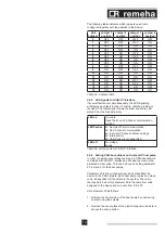
The volume of the buffer vessel (in litres) can be found in the
table below.
Number of Gas HP units
Effective volume* of buffer
vessel in l
1
300
2
500
3
800
4
1000
5
1000
(IIHFWLYHYROXPH YROXPHEHWZHHQÀRZDQGUHWXUQ
connections on the buffer vessel
Table 01 Buffer vessel volume
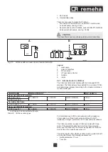
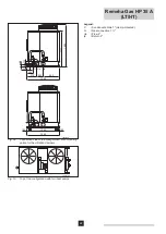
Legend
1 Air
vent
2 Lifting
eye
+HDWSXPSÀRZ
4 Temperature
recorder
5 Temperature
recorder
6 Temperature
recorder
7 Temperature
recorder
8 Temperature
recorders
9
Heat pump return
10 Draining
outlet
11
Separation plate (perforated)
&HQWUDOKHDWLQJV\VWHPÀRZ
13 Effective
volume
14
Central heating system return
4.3 Hydraulic
diagrams
The following examples only give a broad outline of the
principle of heat production.
m
CAUTION
It is important for both the central heating boilers and the heat
SXPSVWKDWWKHFRQ¿JXUDWLRQRIWKHKHDWWUDQVIHUHOHPHQWLV
SDUWRIWKHK\GUDXOLFGHVLJQVLQFHHI¿FLHQF\LQFUHDVHVLIWKH
system is set correctly for both the hydraulics and controls.
T003992-A
1
2
3
9
14
12
11
11
13
8
5
6
10
7
4
Fig. 01
Schematic drawing of the buffer vessel


